CONNECTOR PINOUTS
CONNECTOR PINOUTS
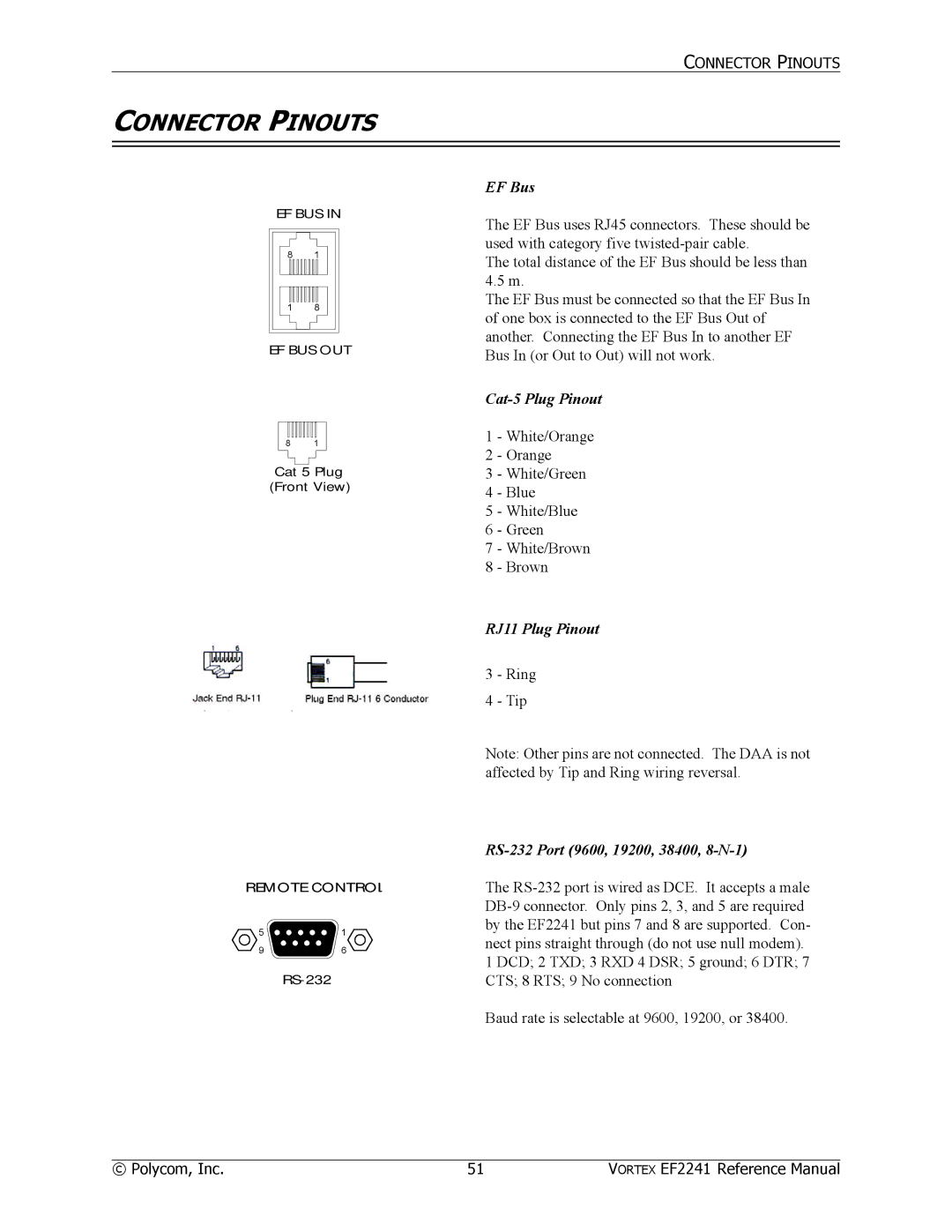
EF BUS IN
8 1
1 8
EF BUS OUT
8 1
Cat 5 Plug
(Front View)
REMOTE CONTROL
5 ![]()
![]()
![]()
![]()
![]() 1
1
96
EF Bus
The EF Bus uses RJ45 connectors. These should be used with category five
The total distance of the EF Bus should be less than 4.5 m.
The EF Bus must be connected so that the EF Bus In of one box is connected to the EF Bus Out of another. Connecting the EF Bus In to another EF Bus In (or Out to Out) will not work.
1 - White/Orange
2 - Orange
3 - White/Green
4 - Blue
5 - White/Blue
6 - Green
7 - White/Brown
8 - Brown
RJ11 Plug Pinout
3 - Ring
4 - Tip
Note: Other pins are not connected. The DAA is not affected by Tip and Ring wiring reversal.
RS-232 Port (9600, 19200, 38400, 8-N-1)
The
Baud rate is selectable at 9600, 19200, or 38400.
© Polycom, Inc. | 51 | VORTEX EF2241 Reference Manual |