Installing The SoundStructure C16, C12, C8, And SR12
the device with no OBAM OUT connection. The device ID is important for ensuring that a system is cabled properly so that it matches the configuration that will be uploaded to the system.
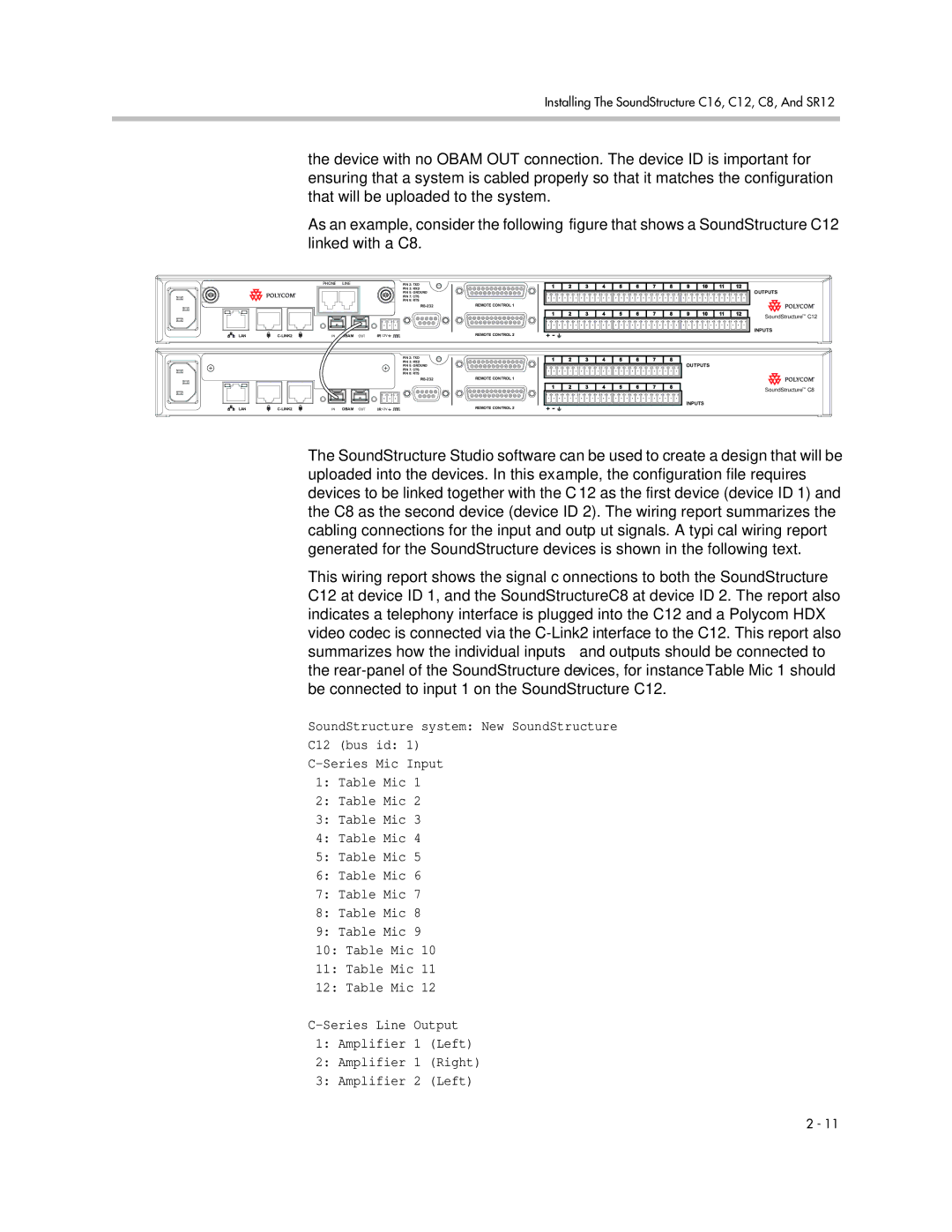
As an example, consider the following figure that shows a SoundStructure C12 linked with a C8.
PHONE LINE | PIN 2: TXD |
| PIN 3: RXD |
| PIN 5: GROUND |
| PIN 7: CTS |
| PIN 8: RTS |
LAN | IN OBAM OUT | IR 12V |
REMOTE CONTROL 1
REMOTE CONTROL 2
1 | 2 | 3 | 4 | 5 | 6 | 7 | 8 | 9 | 10 | 11 | 12 |
1 | 2 | 3 | 4 | 5 | 6 | 7 | 8 | 9 | 10 | 11 | 12 |
OUTPUTS
SoundStructureTM C12
INPUTS
PIN 2: TXD
PIN 3: RXD
PIN 5: GROUND
PIN 7: CTS
PIN 8: RTS
LAN | IN OBAM OUT | IR12V |
REMOTE CONTROL 1
REMOTE CONTROL 2
1 | 2 | 3 | 4 | 5 | 6 | 7 | 8 |
1 | 2 | 3 | 4 | 5 | 6 | 7 | 8 |
OUTPUTS
SoundStructureTM C8
INPUTS
The SoundStructure Studio software can be used to create a design that will be uploaded into the devices. In this example, the configuration file requires devices to be linked together with the C12 as the first device (device ID 1) and the C8 as the second device (device ID 2). The wiring report summarizes the cabling connections for the input and output signals. A typical wiring report generated for the SoundStructure devices is shown in the following text.
This wiring report shows the signal connections to both the SoundStructure C12 at device ID 1, and the SoundStructure C8 at device ID 2. The report also indicates a telephony interface is plugged into the C12 and a Polycom HDX video codec is connected via the
SoundStructure system: New SoundStructure
C12 (bus id: 1)
1:Table Mic 1
2:Table Mic 2
3:Table Mic 3
4:Table Mic 4
5:Table Mic 5
6:Table Mic 6
7:Table Mic 7
8:Table Mic 8
9:Table Mic 9
10:Table Mic 10
11:Table Mic 11
12:Table Mic 12
1:Amplifier 1 (Left)
2:Amplifier 1 (Right)
3:Amplifier 2 (Left)
2 - 11