Hardware Installation Guide for the Polycom SoundStructure C16, C12, C8, And SR12
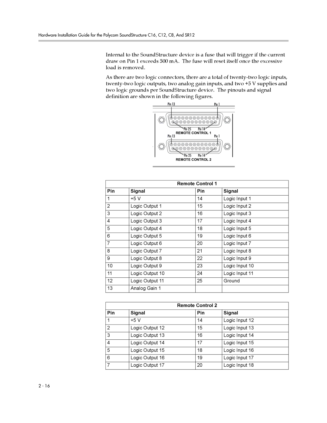
Internal to the SoundStructure device is a fuse that will trigger if the current draw on Pin 1 exceeds 500 mA. The fuse will reset itself once the excessive load is removed.
As there are two logic connectors, there are a total of
Pin 13 | Pin 1 |
| ||||||
|
|
|
|
|
|
|
|
|
|
|
|
|
|
|
|
|
|
|
|
|
|
|
|
|
|
|
|
|
|
|
|
|
|
|
|
|
|
|
|
|
|
|
|
|
|
|
|
|
|
|
|
|
|
|
|
|
|
|
|
|
|
|
| Pin 25 | Pin 14 |
|
| REMOTE CONTROL 1 |
| |
| Pin 13 | Pin 1 |
|
| Pin 25 | Pin 14 |
|
| REMOTE CONTROL 2 |
| |
| Remote Control 1 |
| |
Pin | Signal | Pin | Signal |
1 | +5 V | 14 | Logic Input 1 |
2 | Logic Output 1 | 15 | Logic Input 2 |
3 | Logic Output 2 | 16 | Logic Input 3 |
4 | Logic Output 3 | 17 | Logic Input 4 |
5 | Logic Output 4 | 18 | Logic Input 5 |
6 | Logic Output 5 | 19 | Logic Input 6 |
7 | Logic Output 6 | 20 | Logic Input 7 |
8 | Logic Output 7 | 21 | Logic Input 8 |
9 | Logic Output 8 | 22 | Logic Input 9 |
10 | Logic Output 9 | 23 | Logic Input 10 |
11 | Logic Output 10 | 24 | Logic Input 11 |
12 | Logic Output 11 | 25 | Ground |
13 | Analog Gain 1 |
|
|
| Remote Control 2 |
| |
Pin | Signal | Pin | Signal |
1 | +5 V | 14 | Logic Input 12 |
2 | Logic Output 12 | 15 | Logic Input 13 |
3 | Logic Output 13 | 16 | Logic Input 14 |
4 | Logic Output 14 | 17 | Logic Input 15 |
5 | Logic Output 15 | 18 | Logic Input 16 |
6 | Logic Output 16 | 19 | Logic Input 17 |
7 | Logic Output 17 | 20 | Logic Input 18 |
2 - 16