Hardware Installation Guide for the Polycom SoundStructure C16, C12, C8, and SR12
11 | Logic Output 10 |
| 24 | Logic Input 11 |
12 | Logic Output 11 |
| 25 | Ground |
|
|
|
|
|
13 | Analog Gain 1 |
|
|
|
|
|
|
|
|
|
|
|
| |
|
| Remote Control 2 |
| |
Pin | Signal |
| Pin | Signal |
|
|
|
|
|
1 | +5 V |
| 14 | Logic Input 12 |
|
|
|
|
|
2 | Logic Output 12 |
| 15 | Logic Input 13 |
|
|
|
|
|
3 | Logic Output 13 |
| 16 | Logic Input 14 |
|
|
|
|
|
4 | Logic Output 14 |
| 17 | Logic Input 15 |
|
|
|
|
|
5 | Logic Output 15 |
| 18 | Logic Input 16 |
|
|
|
|
|
6 | Logic Output 16 |
| 19 | Logic Input 17 |
|
|
|
|
|
7 | Logic Output 17 |
| 20 | Logic Input 18 |
|
|
|
|
|
8 | Logic Output 18 |
| 21 | Logic Input 19 |
|
|
|
|
|
9 | Logic Output 19 |
| 22 | Logic Input 20 |
|
|
|
|
|
10 | Logic Output 20 |
| 23 | Logic Input 21 |
|
|
|
|
|
11 | Logic Output 21 |
| 24 | Logic Input 22 |
|
|
|
|
|
12 | Logic Output 22 |
| 25 | Ground |
|
|
|
|
|
13 | Analog Gain 2 |
|
|
|
|
|
|
|
|
Audio Connections
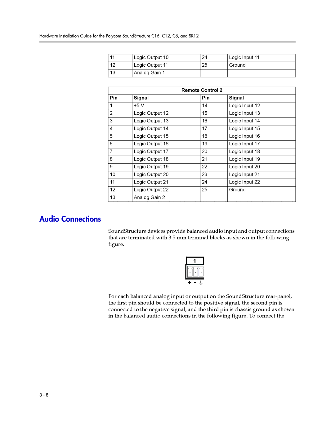
SoundStructure devices provide balanced audio input and output connections that are terminated with 3.5 mm terminal blocks as shown in the following figure.
1
For each balanced analog input or output on the SoundStructure
3 - 8