Installing The SoundStructure C16, C12, C8, And SR12
8 | Logic Output 18 | 21 | Logic Input 19 |
9 | Logic Output 19 | 22 | Logic Input 20 |
|
|
|
|
10 | Logic Output 20 | 23 | Logic Input 21 |
|
|
|
|
11 | Logic Output 21 | 24 | Logic Input 22 |
|
|
|
|
12 | Logic Output 22 | 25 | Ground |
|
|
|
|
13 | Analog Gain 2 |
|
|
|
|
|
|
Logic Inputs
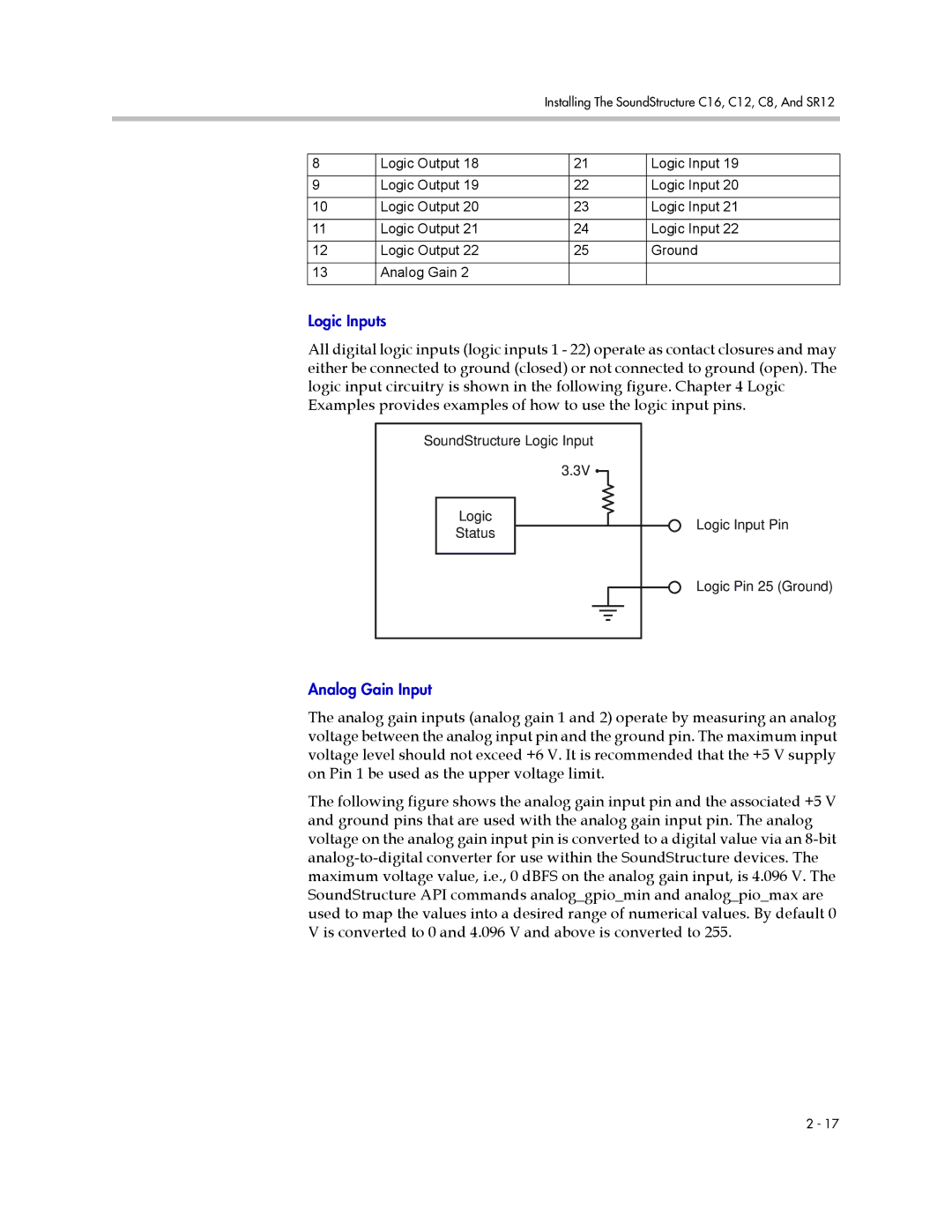
All digital logic inputs (logic inputs 1 - 22) operate as contact closures and may either be connected to ground (closed) or not connected to ground (open). The logic input circuitry is shown in the following figure. Chapter 4 Logic Examples provides examples of how to use the logic input pins.
SoundStructure Logic Input
3.3V ![]()
![]()
Logic
Status
Logic Input Pin
Logic Pin 25 (Ground)
Analog Gain Input
The analog gain inputs (analog gain 1 and 2) operate by measuring an analog voltage between the analog input pin and the ground pin. The maximum input voltage level should not exceed +6 V. It is recommended that the +5 V supply on Pin 1 be used as the upper voltage limit.
The following figure shows the analog gain input pin and the associated +5 V and ground pins that are used with the analog gain input pin. The analog voltage on the analog gain input pin is converted to a digital value via an
2 - 17