Installing The SoundStructure C16, C12, C8, And SR12
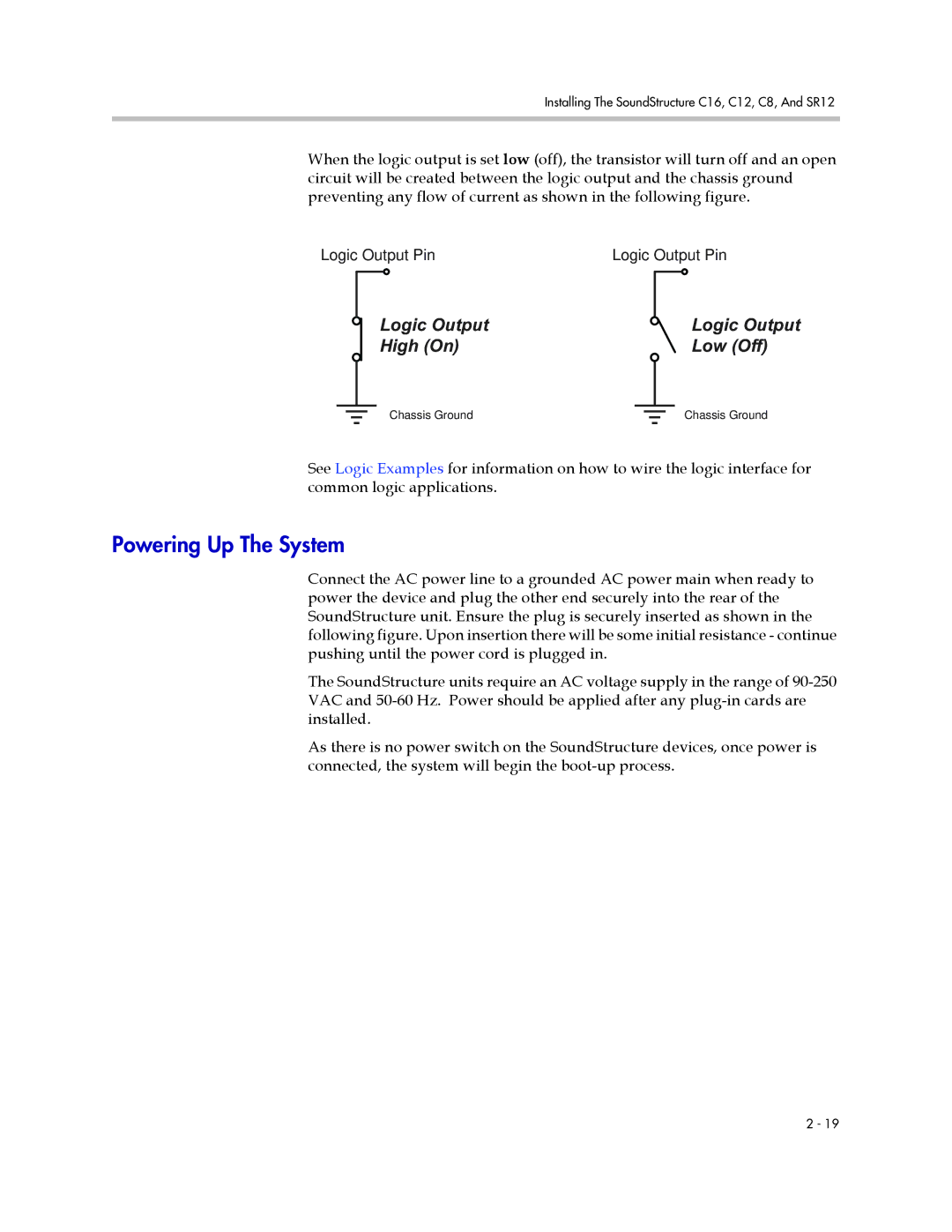
When the logic output is set low (off), the transistor will turn off and an open circuit will be created between the logic output and the chassis ground preventing any flow of current as shown in the following figure.
Logic Output PinLogic Output Pin
Logic Output |
|
|
|
| Logic Output | ||||
High (On) |
|
|
|
| Low (Off) | ||||
|
|
|
|
|
|
|
|
|
|
|
|
|
|
|
|
|
|
|
|
|
|
|
|
|
|
|
| ||
Chassis Ground |
|
|
|
|
|
|
| Chassis Ground | |
|
|
|
|
|
|
| |||
See Logic Examples for information on how to wire the logic interface for common logic applications.
Powering Up The System
Connect the AC power line to a grounded AC power main when ready to power the device and plug the other end securely into the rear of the SoundStructure unit. Ensure the plug is securely inserted as shown in the following figure. Upon insertion there will be some initial resistance - continue pushing until the power cord is plugged in.
The SoundStructure units require an AC voltage supply in the range of
As there is no power switch on the SoundStructure devices, once power is connected, the system will begin the
2 - 19
