Hardware Installation Guide for the Polycom SoundStructure C16, C12, C8, And SR12
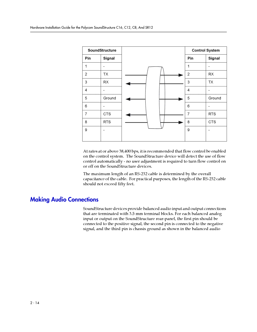
SoundStructure
Pin | Signal |
|
|
1 | - |
|
|
2 | TX |
|
|
3 | RX |
|
|
4 | - |
|
|
5 | Ground |
|
|
6 | - |
|
|
7 | CTS |
|
|
8 | RTS |
|
|
9 | - |
|
|
Control System
Pin | Signal |
|
|
1 | - |
|
|
2 | RX |
|
|
3 | TX |
|
|
4 | - |
|
|
5 | Ground |
|
|
6 | - |
|
|
7 | RTS |
|
|
8 | CTS |
|
|
9 | - |
|
|
At rates at or above 38,400 bps, it is recommended that flow control be enabled on the control system. The SoundStructure device will detect the use of flow control automatically - no user adjustment is required to turn flow control on or off on the SoundStructure devices.
The maximum length of an
Making Audio Connections
SoundStructure devices provide balanced audio input and output connections that are terminated with 3.5 mm terminal blocks. For each balanced analog input or output on the SoundStructure
2 - 14