Return to Section TOC Return to Master TOC
TROUBLESHOOTING AND REPAIR |
MONITOR AND PEDESTAL REMOVAL AND REPLACEMENT PROCEDURE
(continued)
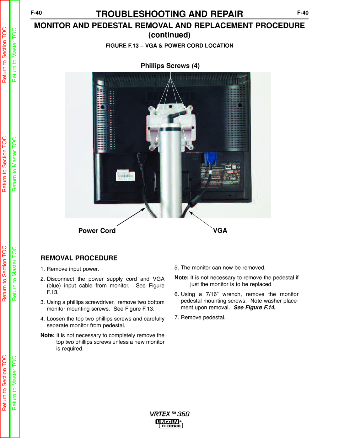
FIGURE F.13 – VGA & POWER CORD LOCATION
Phillips Screws (4)
Return to Master TOC
Return to Section TOC
Power Cord | VGA |
Return to Section TOC Return to Master TOC
Return to Section TOC Return to Master TOC
REMOVAL PROCEDURE 1. Remove input power.
2. Disconnect the power supply cord and VGA (blue) input cable from monitor. See Figure F.13.
3. Using a phillips screwdriver, remove two bottom monitor mounting screws. See Figure F.13.
4. Loosen the top two phillips screws and carefully separate monitor from pedestal.
It is not necessary to completely remove the Note: top two phillips screws unless a new monitor
is required.
5. The monitor can now be removed.
It is not necessary to remove the pedestal if Note: just the monitor is to be replaced
6. Using a 7/16” wrench, remove the monitor pedestal mounting screws. Note washer place- ment upon removal. See Figure F.14.
7. Remove pedestal.
VRTEX TM 360