Return to Section TOC Return to Master TOC
Return to Section TOC Return to Master TOC
Return to Section TOC Return to Master TOC
| OPERATION |
|
| ||||||
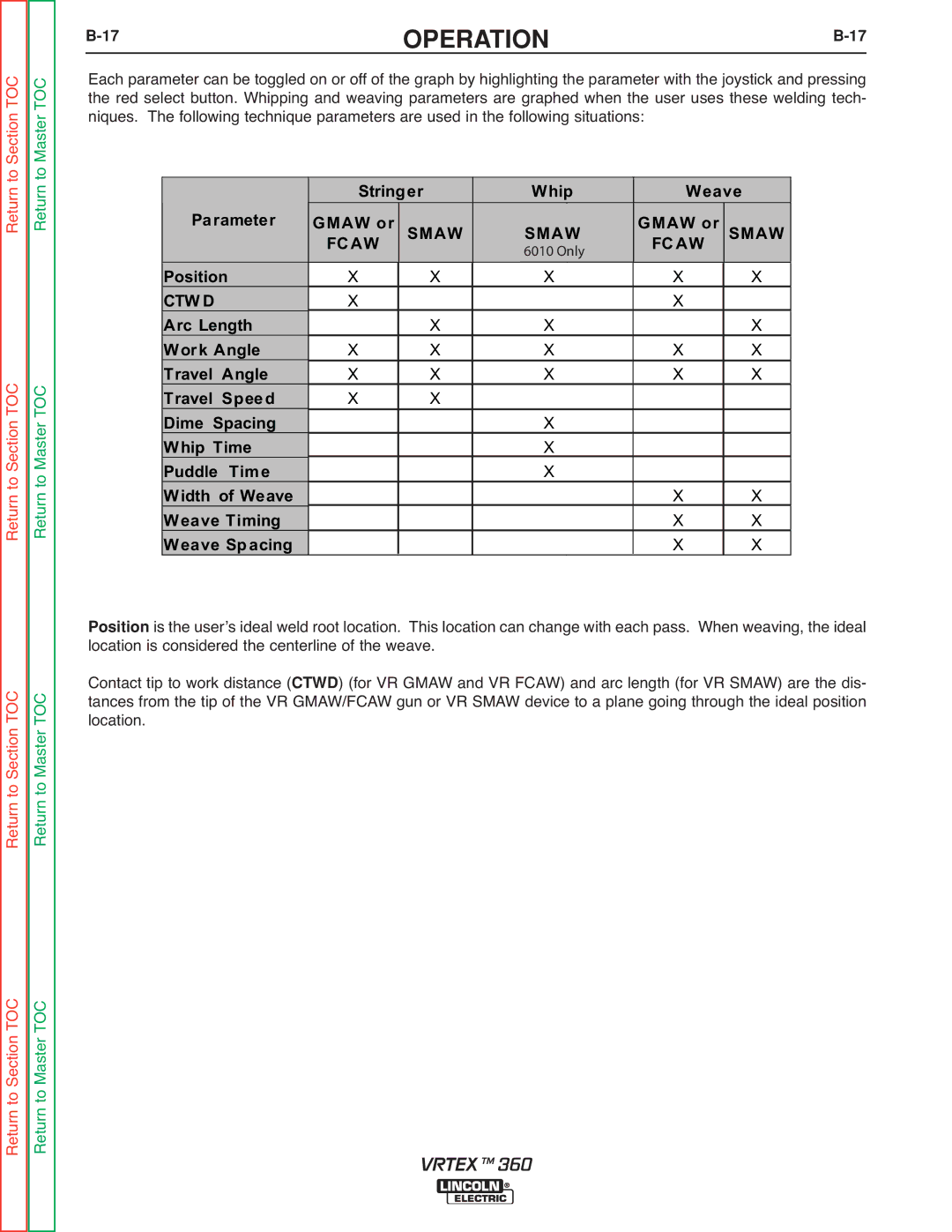
Each parameter can be toggled on or off of the graph by highlighting the parameter with the joystick and pressing | |||||||||
the red select button. Whipping and weaving parameters are graphed when the user uses these welding tech- | |||||||||
niques. The following technique parameters are used in the following situations: |
|
| |||||||
|
|
|
|
|
|
|
|
|
|
|
| Stringer |
| Whip | Weave |
| |||
| Parameter | GMAW or | SMAW |
| SMAW |
| GMAW or | SMAW |
|
|
|
|
|
| |||||
|
| FCAW | FCAW | ||||||
|
|
|
| 6010 Only |
|
|
| ||
|
|
|
|
|
|
|
|
| |
| Position | X | X |
| X | X | X |
| |
| CTW D | X |
|
|
|
| X |
|
|
| Arc Length |
| X |
| X |
| X |
| |
| Work Angle | X | X |
| X | X | X |
| |
| Travel Angle | X | X |
| X | X | X |
| |
| Travel Speed | X | X |
|
|
|
|
|
|
| Dime Spacing |
|
|
| X |
|
|
| |
| Whip Time |
|
|
| X |
|
|
| |
| Puddle Time |
|
|
| X |
|
|
| |
| Width of Weave |
|
|
|
|
| X | X |
|
| Weave Timing |
|
|
|
|
| X | X |
|
| Weave Spacing |
|
|
|
|
| X | X |
|
is the userʼs ideal weld root location. This location can change with each pass. When weaving, the ideal locationPositionis considered the centerline of the weave.
Contact tip to work distance ( ) (for VR GMAW and VR FCAW) and arc length (for VR SMAW) are the dis- tances from the tip of the VR CTWDGMAW/FCAW gun or VR SMAW device to a plane going through the ideal position location.
Return to Master TOC
Return to Section TOC
VRTEX TM 360