Return to Section TOC Return to Master TOC
Return to Section TOC Return to Master TOC
Return to Section TOC Return to Master TOC
Return to Section TOC Return to Master TOC
TROUBLESHOOTING AND REPAIR |
|
|
| ||||||
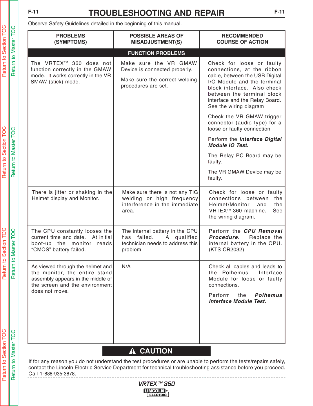
Observe Safety Guidelines detailed in the beginning of this manual. |
|
|
|
|
| ||||
PROBLEMS |
| POSSIBLE AREAS OF | RECOMMENDED |
| |||||
(SYMPTOMS) |
| MISADJUSTMENT(S) | COURSE OF ACTION |
| |||||
|
|
|
|
|
|
|
| ||
|
| FUNCTION PROBLEMS |
|
|
|
|
| ||
The VRTEXTM 360 does not | Make sure the VR GMAW | Check for loose or faulty | |||||||
function correctly in the GMAW | Device is connected properly. | connections, | at | the ribbon | |||||
mode. It works correctly in the VR | Make sure the correct welding | cable, between the USB Digital | |||||||
SMAW (stick) mode. |
| I/O Module and the terminal | |||||||
|
| procedures are set. |
| block interface. | Also check | ||||
|
|
|
|
| between the terminal block | ||||
|
|
|
|
| interface and the Relay Board. | ||||
|
|
|
|
| See the wiring diagram |
| |||
|
|
|
|
| Check the VR GMAW trigger | ||||
|
|
|
|
| connector (audio type) for a | ||||
|
|
|
|
| loose or faulty connection. |
| |||
|
|
|
|
| Perform the Interface Digital | ||||
|
|
|
|
| Module IO Test. |
|
| ||
|
|
|
|
| The Relay PC Board may be | ||||
|
|
|
|
| faulty. |
|
|
|
|
|
|
|
|
| The VR GMAW Device may be | ||||
|
|
|
|
| faulty. |
|
|
|
|
There is jitter or shaking in the | Make sure there is not any TIG | Check for loose or faulty | |||||||
Helmet display and Monitor. | welding or | high | frequency | connections | between | the | |||
|
| interference in the immediate | Helmet/Monitor | and | the | ||||
|
| area. |
|
| VRTEXTM 360 machine. | See | |||
|
|
|
|
| the wiring diagram. |
| |||
The CPU constantly looses the | The internal battery in the CPU | Perform | the | CPU Removal | |||||
current time and date. | At initial | has failed. | A | qualified | Procedure. | Replace | the | ||
technician needs to address this | internal battery in the CPU. | ||||||||
“CMOS” battery failed. |
| problem. |
|
| (KTS CR2032) |
|
| ||
As viewed through the helmet and | N/A |
|
| Check all cables and leads to | |||||
the monitor, the entire stand |
|
|
| the Polhemus | Interface | ||||
assembly appears in the middle of |
|
|
| Module for loose or faulty | |||||
the screen and the environment |
|
|
| connections. |
|
|
| ||
does not move. |
|
|
|
| Perform | the | Polhemus | ||
|
|
|
|
| Interface Module Test. |
| |||
|
|
|
|
|
|
|
|
|
|
CAUTION
If for any reason you do not understand the test procedures or are unable to perform the tests/repairs safely, contact the Lincoln Electric Service Department for technical troubleshooting assistance before you proceed. Call
VRTEX TM 360