Return to Section TOC Return to Master TOC
INSTALLATION | ||
| 8. Remove the monitor from the back of the machine. | |
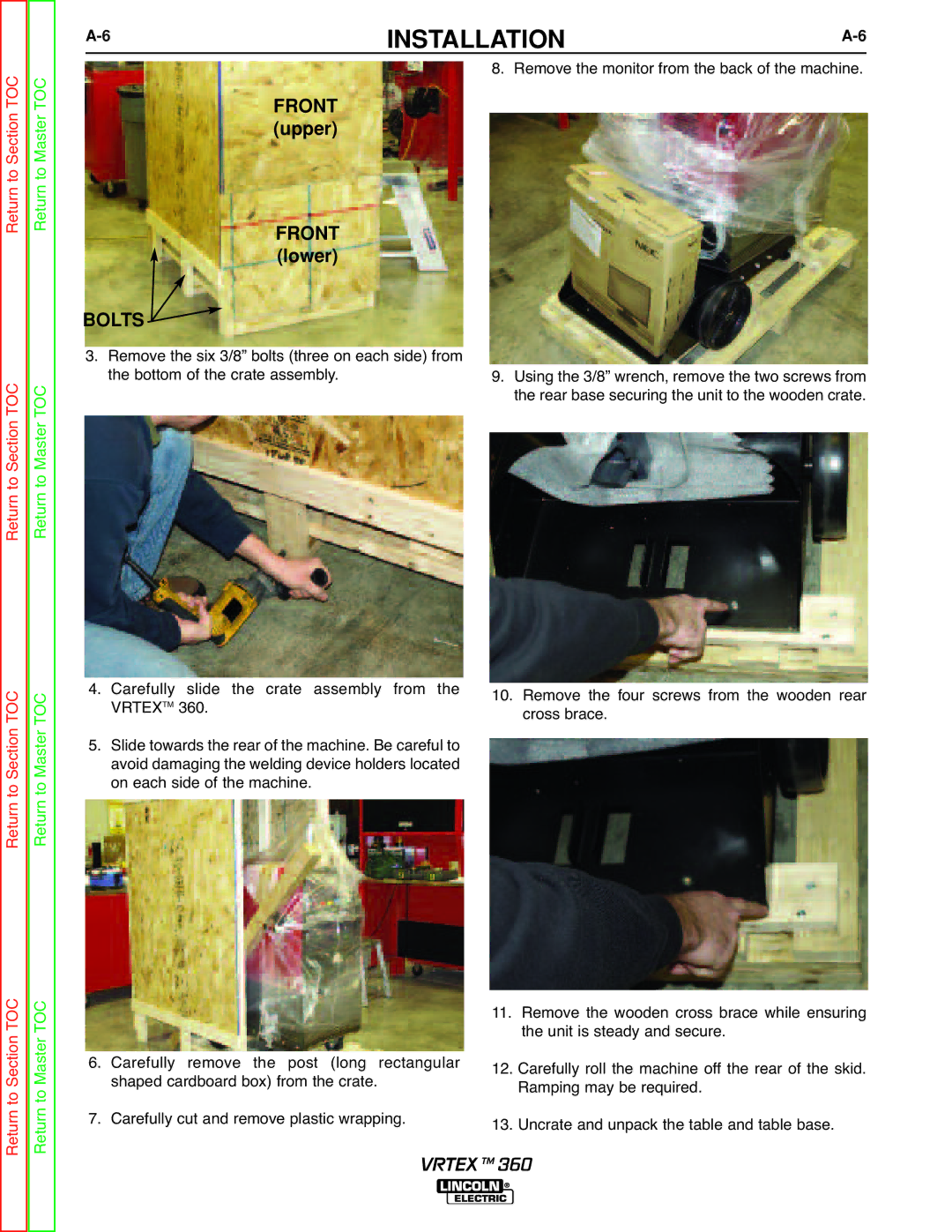
FRONT (upper)
Return to Section TOC Return to Master TOC
FRONT (lower)
BOLTS 
3. Remove the six 3/8” bolts (three on each side) from the bottom of the crate assembly.
9.Using the 3/8” wrench, remove the two screws from the rear base securing the unit to the wooden crate.
Return to Section TOC Return to Master TOC
4.Carefully slide the crate assembly from the
VRTEXTM 360.
5.Slide towards the rear of the machine. Be careful to avoid damaging the welding device holders located on each side of the machine.
10.Remove the four screws from the wooden rear cross brace.
Return to Section TOC Return to Master TOC
6.Carefully remove the post (long rectangular shaped cardboard box) from the crate.
7.Carefully cut and remove plastic wrapping.
11.Remove the wooden cross brace while ensuring the unit is steady and secure.
12.Carefully roll the machine off the rear of the skid. Ramping may be required.
13.Uncrate and unpack the table and table base.
VRTEX TM 360