Return to Section TOC Return to Master TOC
TROUBLESHOOTING AND REPAIR |
POLHEMUS MODULE REMOVAL AND REPLACEMENT
PROCEDURE (continued)
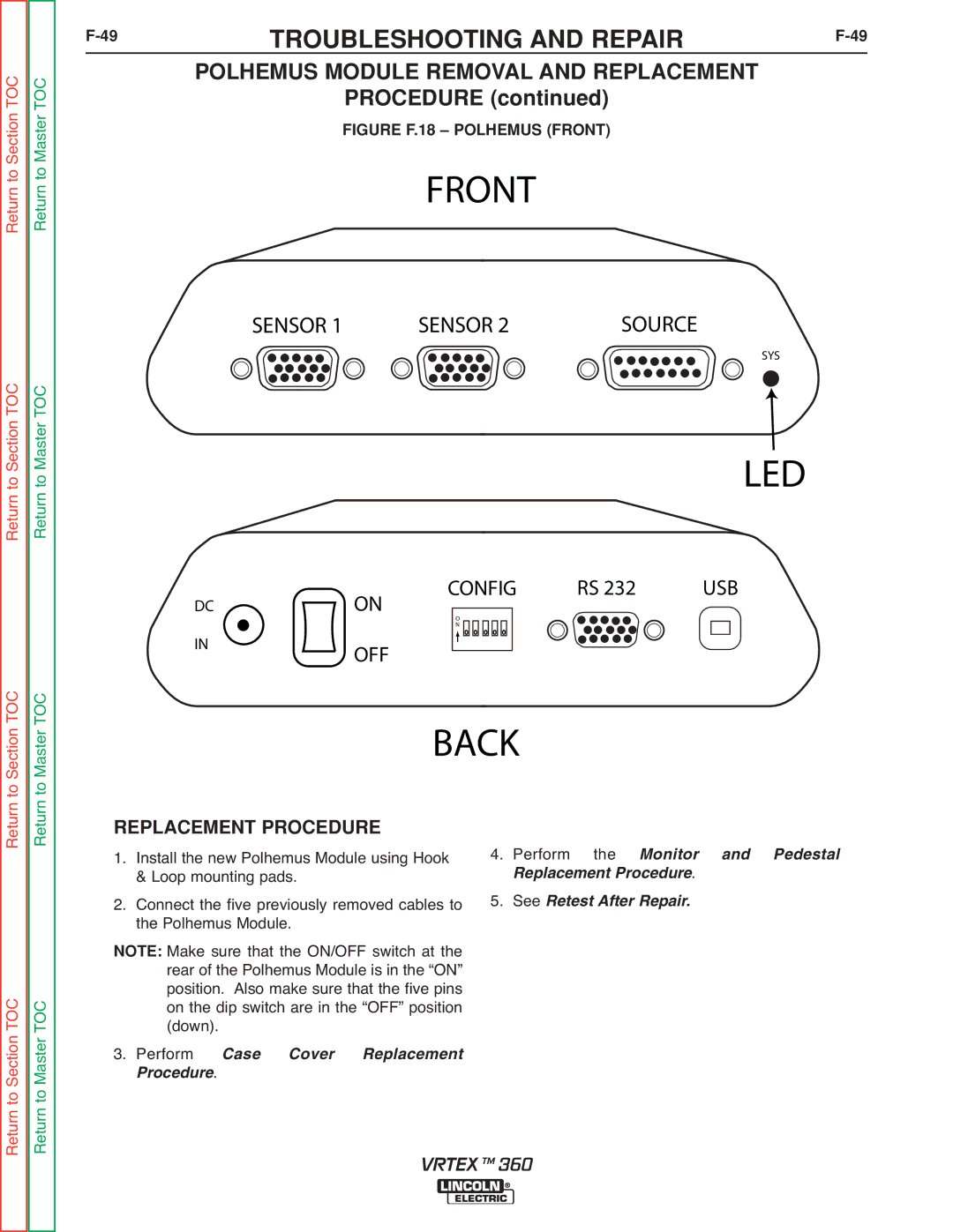
FIGURE F.18 – POLHEMUS (FRONT)
FRONT
Return to Section TOC Return to Master TOC
SENSOR 1 | SENSOR 2 | SOURCE |
SYS
LED
CONFIG | RS 232 | USB |
DCON
to Section TOC to Master TOC
IN
O
N
OFF
BACK
Return Return
Return to Section TOC Return to Master TOC
REPLACEMENT PROCEDURE
1. Install the new Polhemus Module using Hook & Loop mounting pads.
2. Connect the five previously removed cables to the Polhemus Module.
Make sure that the ON/OFF switch at the NOTE: rear of the Polhemus Module is in the “ON” position. Also make sure that the five pins on the dip switch are in the “OFF” position
(down).
3. Perform . Case Cover Replacement
Procedure
4.Perform the Monitor. and Pedestal SeeR placement Procedure
5.Retest After Repair.
VRTEX TM 360