Return to Section TOC Return to Master TOC
Return to Section TOC Return to Master TOC
TROUBLESHOOTING AND REPAIR |
5VDC SUPPLY MODULE REMOVAL AND REPLACEMENT PROCEDURE
(continued)
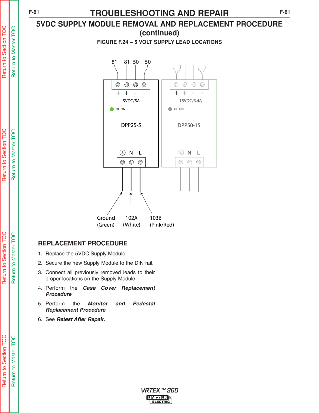
FIGURE F.24 – 5 VOLT SUPPLY LEAD LOCATIONS
81 81 50 50
+ + - - | + + - - |
5VDC/5A | 15VDC/3.4A |
DC ON | DC ON |
N L | N L |
Return to Section TOC Return to Master TOC
Return to Section TOC Return to Master TOC
Ground 102A 103B (Green) (White) (Pink/Red)
REPLACEMENT PROCEDURE | |||
1. | Replace the 5VDC Supply Module. | ||
2. | Secure the new Supply Module to the DIN rail. | ||
3. | Connect all previously removed leads to their | ||
4. | proper locations on the Supply Module. | ||
Perform | the | Case Cover Replacement | |
5. | rocedure. |
| |
Perform | the | Monitor and Pedestal | |
6. | R placement Procedure. | ||
See Retest After Repair. | |||
VRTEX TM 360