Return to Section TOC Return to Master TOC
F-32 TROUBLESHOOTING AND REPAIRF-32
USB INTERFACE MODULE TEST PROCEDURE (continued)
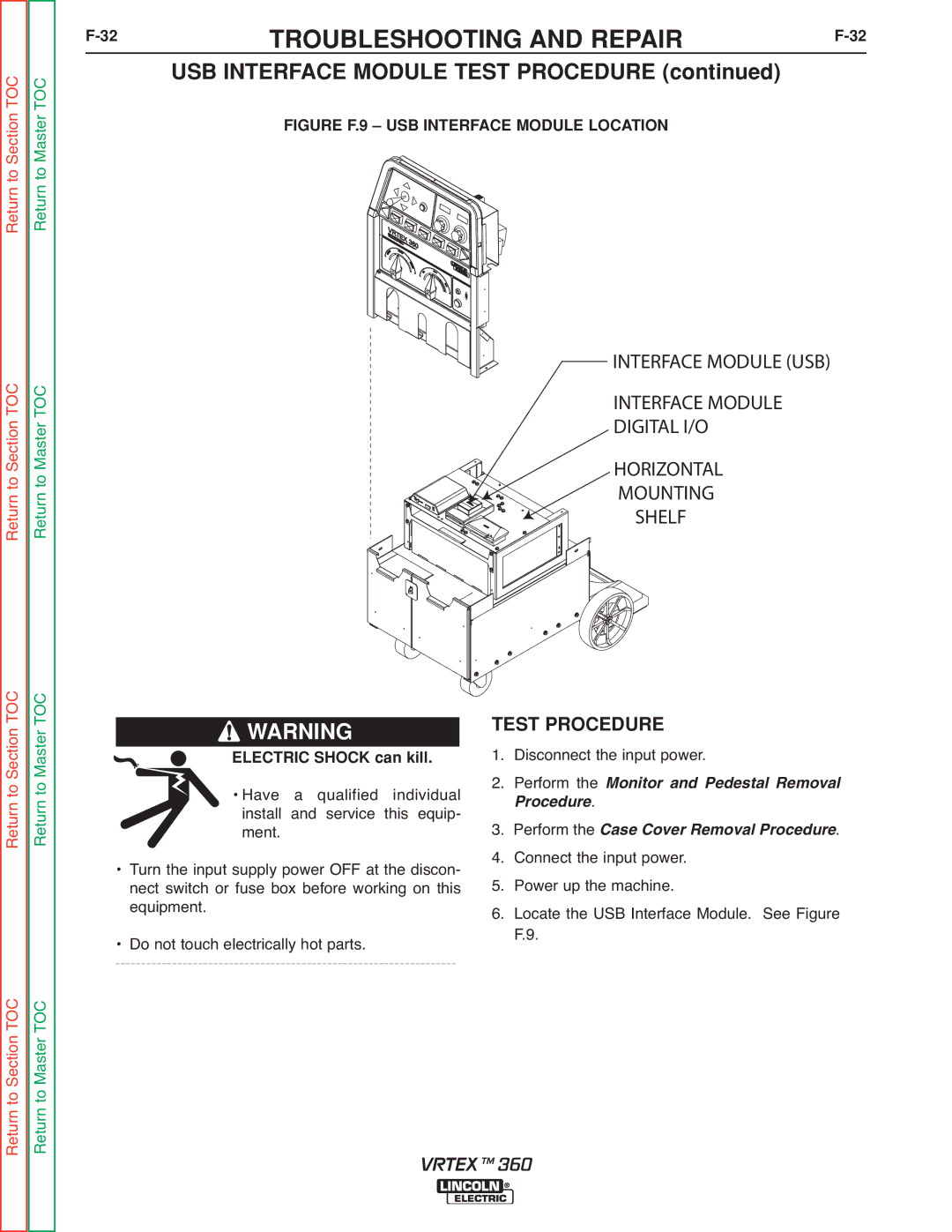
FIGURE F.9 – USB INTERFACE MODULE LOCATION
Return to Section TOC Return to Master TOC
INTERFACE MODULE (USB)
INTERFACE MODULE DIGITAL I/O
HORIZONTAL
MOUNTING
SHELF
Return to Section TOC Return to Master TOC
Return to Section TOC Return to Master TOC
![]() WARNING
WARNING
ELECTRIC SHOCK can kill.
• Have a qualified individual install and service this equip- ment.
• Turn the input supply power OFF at the discon- nect switch or fuse box before working on this equipment.
• Do not touch electrically hot parts.
TEST PROCEDURE
1. Disconnect the input power.
2. Perform the
. Monitor and Pedestal Removal rocedure
3. Perform theRemoval Procedure.
4. Connect theCaseinput Covpower.
5. Power up the machine.
6. Locate the USB Interface Module. See Figure F.9.
VRTEX TM 360