Return to Section TOC Return to Master TOC
Return to Section TOC Return to Master TOC
F-16 TROUBLESHOOTING AND REPAIRF-16
5 VDC SUPPLY TEST PROCEDURE (continued)
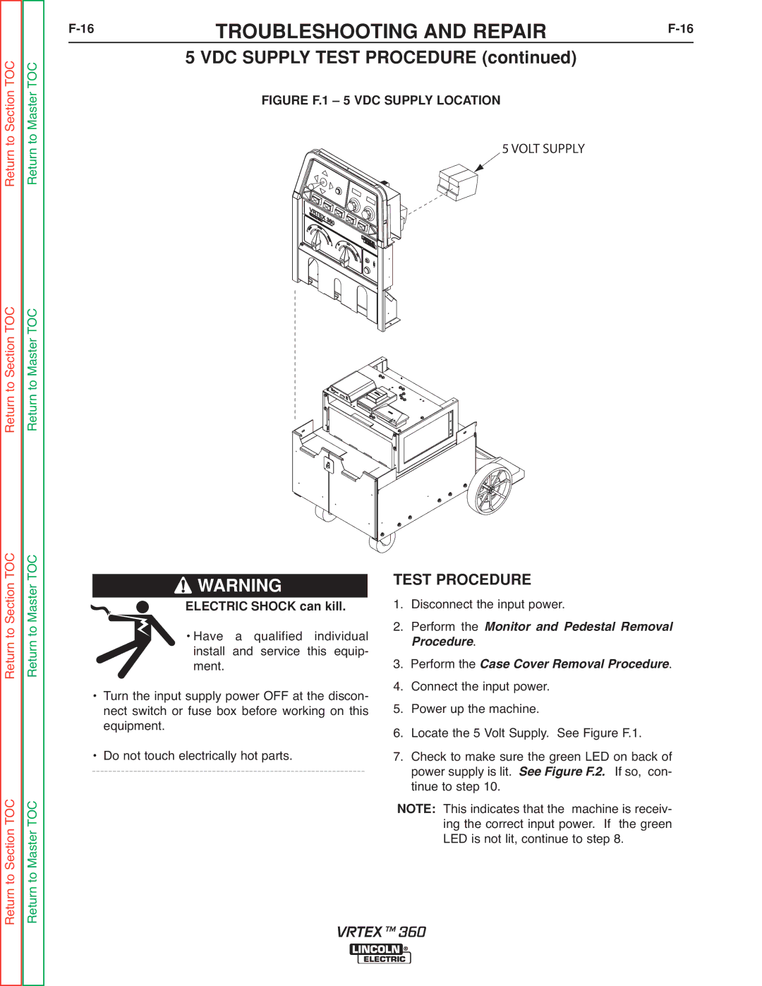
FIGURE F.1 – 5 VDC SUPPLY LOCATION
5 VOLT SUPPLY
Return to Section TOC Return to Master TOC
Return to Section TOC Return to Master TOC
![]() WARNING
WARNING
ELECTRIC SHOCK can kill.
• Have a qualified individual install and service this equip- ment.
• Turn the input supply power OFF at the discon- nect switch or fuse box before working on this equipment.
• Do not touch electrically hot parts.
TEST PROCEDURE |
| |
1. | Disconnect the input power. | |
2. | Perform the Monitor and Pedestal Removal | |
3. | rocedure. | Removal Procedure. |
Perform the Case Cov | ||
4. | Connect the input power. |
|
5. | Power up the machine. |
|
6. | Locate the 5 Volt Supply. See Figure F.1. | |
7. | Check to make sure the green LED on back of | |
| power supply is lit. See Figure F.2. If so, con- | |
| tinue to step 10. |
|
This indicates that the machine is receiv- NOTE: ing the correct input power. If the green
LED is not lit, continue to step 8.
VRTEX TM 360