Return to Section TOC Return to Master TOC
Return to Section TOC Return to Master TOC
TROUBLESHOOTING AND REPAIR |
MOTOR CONTROL BOARD
REMOVAL AND REPLACEMENT PROCEDURE (continued)
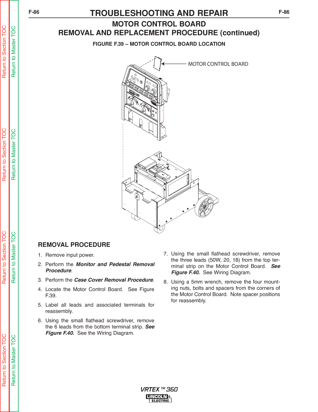
FIGURE F.39 – MOTOR CONTROL BOARD LOCATION
![]() MOTOR CONTROL BOARD
MOTOR CONTROL BOARD
Return to Section TOC Return to Master TOC
Return to Section TOC Return to Master TOC
REMOVAL PROCEDURE | ||
1. | Remove input power. | |
2. | Perform the Monitor and Pedestal Removal | |
3. | rocedure. | ver Removal Procedure. |
Perform the Case | ||
4. | Locate the Motor | Control Board. See Figure |
5. | F.39. |
|
Label all leads and associated terminals for | ||
6. | reassembly. |
|
Using the small flathead screwdriver, remove | ||
| the 6 leads from the bottom terminal strip. See | |
| Figure F.40. See the Wiring Diagram. | |
7.Using the small flathead screwdriver, remove the three leads (50W, 20, 18) from the top ter- minal strip on the Motor Control Board.
See Wiring Diagram. See
8.Using a 5mm wrench, remove the four mount- ing nuts, bolts and spacers from the corners of the Motor Control Board. Note spacer positions for reassembly.Figure F.40.
VRTEX TM 360