Return to Section TOC Return to Master TOC
TROUBLESHOOTING AND REPAIR |
VGA SPLITTER REMOVAL AND REPLACEMENT PROCEDURE (continued)
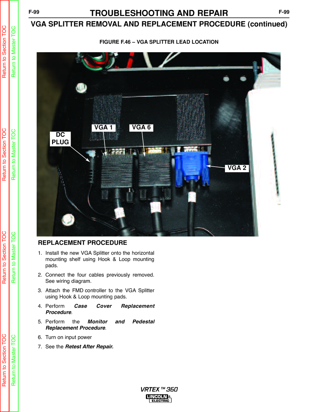
FIGURE F.46 – VGA SPLITTER LEAD LOCATION
Return to Section TOC Return to Master TOC
VGA 1 | VGA 6 |
DC
PLUG
 VGA 2
VGA 2
Return to Section TOC Return to Master TOC
Return to Section TOC Return to Master TOC
REPLACEMENT PROCEDURE | |||||
1. | Install the new VGA Splitter onto the horizontal | ||||
| mounting shelf using Hook & Loop mounting | ||||
2. | pads. |
|
|
|
|
Connect the four cables previously removed. | |||||
3. | See wiring diagram. |
| |||
Attach the FMD controller to the VGA Splitter | |||||
4. | using Hook & Loop mounting pads. | ||||
Perform |
| Case | Cover | Replacement | |
5. | rocedure. |
|
|
| |
Perform | the | Monitor | and Pedestal | ||
6. | Replacement Procedure. |
| |||
Turn on input power |
| ||||
7. | See the | Retest After Repair. |
| ||
VRTEX TM 360