Return to Section TOC Return to Master TOC
THEORY OF OPERATION | ||
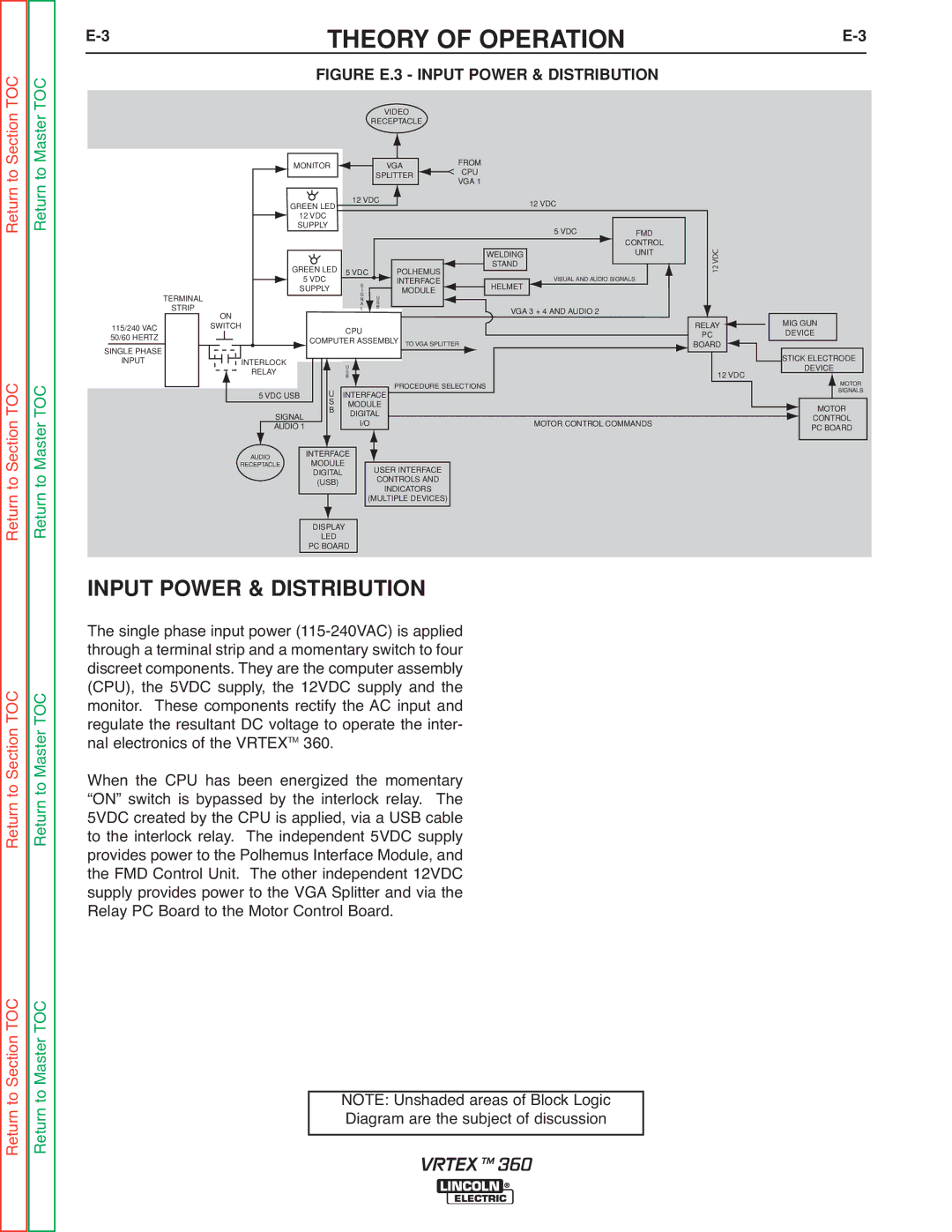
| FIGURE E.3 - INPUT POWER & DISTRIBUTION |
|
VIDEO
RECEPTACLE
|
|
|
|
|
|
|
| FROM |
MONITOR |
|
| VGA |
|
| < | ||
|
|
|
| CPU | ||||
|
|
| SPLITTER |
|
| |||
|
|
|
|
|
| VGA 1 | ||
|
|
|
|
|
|
|
| |
|
|
|
|
|
|
|
| |
GREEN LED |
| 12 VDC |
|
|
|
| 12 VDC | |
|
|
|
|
|
|
| ||
|
|
|
|
|
|
|
| |
12 VDC |
|
|
|
|
|
|
|
|
SUPPLY |
|
|
|
|
|
|
|
|
TERMINAL
STRIP
115/240 VAC 50/60 HERTZ
SINGLE PHASE
ON
SWITCH
GREEN LED |
|
|
|
|
5 VDC |
|
| POLHEMUS | |
5 VDC |
|
|
| INTERFACE |
S |
|
| ||
SUPPLY |
|
| MODULE | |
I |
|
| ||
| G | U |
| |
| N |
| ||
| A | S |
| |
| L | B |
| |
CPU
![]() COMPUTER ASSEMBLY TO VGA SPLITTER
COMPUTER ASSEMBLY TO VGA SPLITTER
|
| 5 VDC | FMD | |
|
|
| CONTROL | |
WELDING |
|
| UNIT | |
|
|
|
| |
STAND |
| VISUAL AND AUDIO SIGNALS |
| |
|
| |||
|
|
| ||
HELMET |
|
|
|
|
|
|
|
|
|
VGA 3 + 4 AND AUDIO 2 |
|
| ||
12 VDC
RELAY ![]() PC
PC
![]() BOARD
BOARD ![]()
MIG GUN
DEVICE
Section TOC Master TOC
INPUT
INTERLOCK |
|
|
| U |
|
|
| |
RELAY |
|
|
| S |
|
|
| |
|
|
|
| U | B |
| PROCEDURE SELECTIONS | |
|
|
|
|
|
| |||
5 VDC USB |
|
| INTERFACE |
|
| |||
|
|
|
| S | MODULE |
|
| |
|
|
|
|
|
| |||
|
|
|
| B |
|
| ||
| SIGNAL |
| DIGITAL |
|
| |||
|
|
|
|
| ||||
|
|
|
| I/O |
| MOTOR CONTROL COMMANDS | ||
| AUDIO 1 |
|
|
|
| |||
|
|
|
|
|
|
|
|
|
|
|
|
|
|
|
|
|
|
12 VDC
STICK ELECTRODE
DEVICE
MOTOR
SIGNALS
MOTOR
CONTROL
PC BOARD
Return to Return to
Return to Section TOC Return to Master TOC
AUDIO | INTERFACE |
|
| |
MODULE |
|
| ||
RECEPTACLE |
| USER INTERFACE | ||
| DIGITAL |
| ||
|
| CONTROLS AND | ||
| (USB) |
| ||
|
| INDICATORS | ||
|
|
|
| |
|
|
|
| (MULTIPLE DEVICES) |
|
|
|
|
|
|
|
|
|
|
| DISPLAY |
|
| |
| LED |
|
| |
| PC BOARD |
|
| |
INPUT POWER & DISTRIBUTION
The single phase input power
When the CPU has been energized the momentary “ON” switch is bypassed by the interlock relay. The 5VDC created by the CPU is applied, via a USB cable to the interlock relay. The independent 5VDC supply provides power to the Polhemus Interface Module, and the FMD Control Unit. The other independent 12VDC supply provides power to the VGA Splitter and via the Relay PC Board to the Motor Control Board.
Return to Section TOC Return to Master TOC
NOTE: Unshaded areas of Block Logic Diagram are the subject of discussion
VRTEX TM 360