Return to Section TOC Return to Master TOC
TROUBLESHOOTING AND REPAIR |
INTERFACE MODULE DIGITAL I/O
REMOVAL AND REPLACEMENT PROCEDURE (continued)
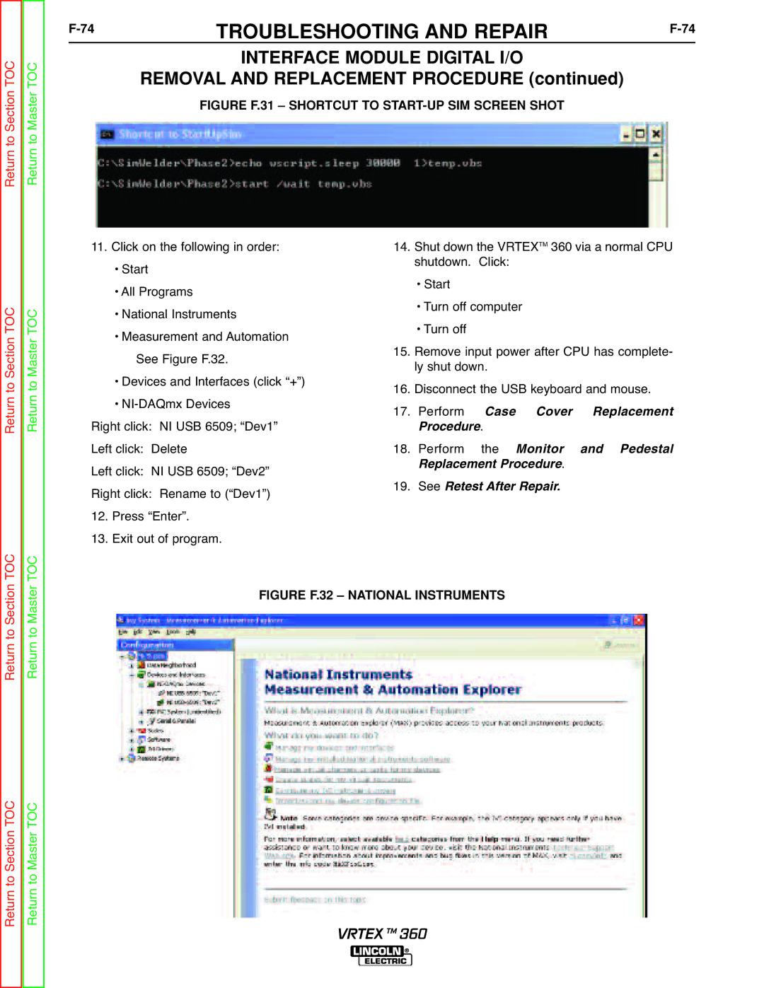
FIGURE F.31 – SHORTCUT TO START-UP SIM SCREEN SHOT
Return to Section TOC Return to Master TOC
11. Click on the following in order:
• Start
• All Programs
• National Instruments
• Measurement and Automation See Figure F.32.
• Devices and Interfaces (click “+”)
•
Right click: NI USB 6509; “Dev1”
Left click: Delete
Left click: NI USB 6509; “Dev2”
Right click: Rename to (“Dev1”)
12. Press “Enter”.
13. Exit out of program.
14.Shut down the VRTEXTM 360 via a normal CPU shutdown. Click:
•Start
•Turn off computer
•Turn off
15.Remove input power after CPU has complete- ly shut down.
16.Disconnect the USB keyboard and mouse.
17.Perform .Case Cover Replacement
18.Performrocedurethe Monitor. and Pedestal RSeeplacement Procedure
19.Retest After Repair.
Return to Section TOC Return to Master TOC
FIGURE F.32 – NATIONAL INSTRUMENTS
Return to Master TOC
Return to Section TOC
VRTEX TM 360