Return to Section TOC Return to Master TOC
TROUBLESHOOTING AND REPAIR |
INTERFACE MODULE DIGITAL I/O
REMOVAL AND REPLACEMENT PROCEDURE (continued)
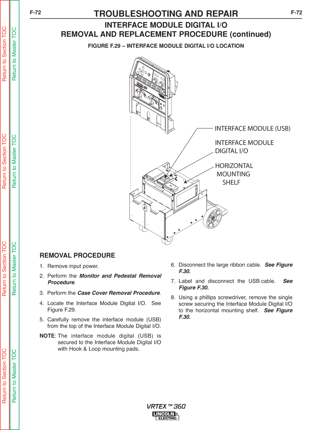
FIGURE F.29 – INTERFACE MODULE DIGITAL I/O LOCATION
Return to Section TOC Return to Master TOC
INTERFACE MODULE (USB)
INTERFACE MODULE DIGITAL I/O
HORIZONTAL
MOUNTING
SHELF
Return to Section TOC Return to Master TOC
Return to Section TOC Return to Master TOC
REMOVAL PROCEDURE 1. Remove input power.
2. Perform the
. Monitor and Pedestal Removal rocedure
3. Perform the Case Cover Removal Procedure.
4. Locate the Interface Module Digital I/O. See Figure F.29.
5. Carefully remove the interface module (USB) from the top of the Interface Module Digital I/O.
: The interface module digital (USB) is NOTE secured to the Interface Module Digital I/O
with Hook & Loop mounting pads.
6.Disconnect the large ribbon cable. See Figure
F.30.
7.Label and disconnect the USB cable. See
Figure F.30.
8.Using a phillips screwdriver, remove the single screw securing the Interface Module Digital I/O to the horizontal mounting shelf. See Figure
F.30.
VRTEX TM 360
