Return to Section TOC Return to Master TOC
THEORY OF OPERATION |
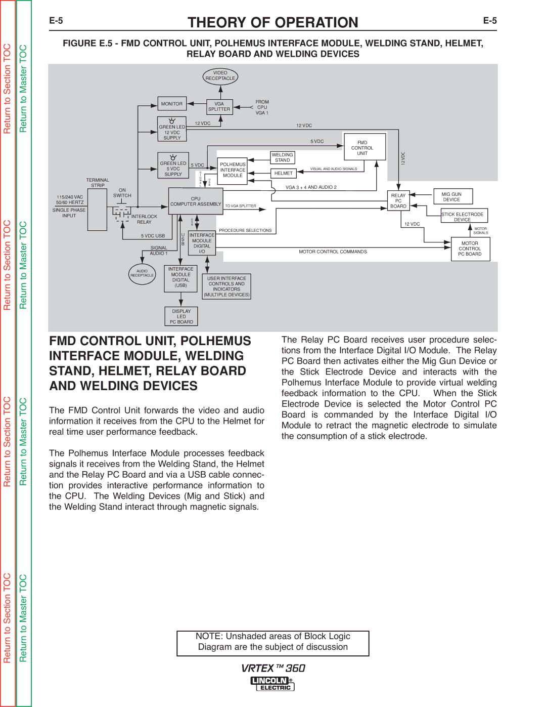
FIGURE E.5 - FMD CONTROL UNIT, POLHEMUS INTERFACE MODULE, WELDING STAND, HELMET,
RELAY BOARD AND WELDING DEVICES
VIDEO
RECEPTACLE
|
|
|
|
|
|
|
| FROM |
MONITOR |
|
| VGA |
|
| < | ||
|
|
|
| CPU | ||||
|
|
| SPLITTER |
|
| |||
|
|
|
|
|
| VGA 1 | ||
|
|
|
|
|
|
|
| |
|
|
|
|
|
|
|
| |
GREEN LED |
| 12 VDC |
|
|
|
| 12 VDC | |
|
|
|
|
|
|
| ||
|
|
|
|
|
|
|
| |
12 VDC |
|
|
|
|
|
|
|
|
SUPPLY |
|
|
|
|
|
|
|
|
TERMINAL
STRIP
115/240 VAC 50/60 HERTZ
SINGLE PHASE
ON
SWITCH
GREEN LED |
|
|
|
|
|
5 VDC |
|
| POLHEMUS | ||
5 VDC |
| S |
|
| INTERFACE |
SUPPLY |
|
|
| MODULE | |
| I |
|
| ||
|
| G | U |
| |
|
| N |
| ||
|
| A | S |
| |
|
| L | B |
| |
|
|
|
|
|
|
CPU
![]() COMPUTER ASSEMBLY TO VGA SPLITTER
COMPUTER ASSEMBLY TO VGA SPLITTER
|
| 5 VDC | FMD | |
|
|
| CONTROL | |
WELDING |
|
| UNIT | |
|
|
|
| |
STAND |
| VISUAL AND AUDIO SIGNALS |
| |
|
| |||
|
|
| ||
HELMET |
|
|
|
|
|
|
|
|
|
VGA 3 + 4 AND AUDIO 2 |
|
| ||
12 VDC
RELAY ![]() PC
PC
![]() BOARD
BOARD ![]()
MIG GUN
DEVICE
Section TOC Master TOC
INPUT
INTERLOCK |
|
|
| U |
|
|
|
| |
RELAY |
|
|
| S |
|
|
|
| |
|
|
|
| U | B |
| PROCEDURE SELECTIONS | ||
|
|
|
|
|
| ||||
5 VDC USB |
|
| INTERFACE |
|
|
| |||
|
|
|
| S | MODULE |
|
|
| |
|
|
|
|
|
|
| |||
|
|
|
| B |
|
|
| ||
| SIGNAL |
| DIGITAL |
|
|
| |||
|
|
|
|
|
| ||||
|
|
|
| I/O |
|
| MOTOR CONTROL COMMANDS | ||
| AUDIO 1 |
|
|
|
|
| |||
|
|
|
|
|
|
|
|
|
|
|
|
|
|
|
|
|
|
|
|
12 VDC
STICK ELECTRODE
DEVICE
MOTOR
SIGNALS
MOTOR
CONTROL
PC BOARD
Return to Return to
AUDIO | INTERFACE |
|
| |
MODULE |
|
| ||
RECEPTACLE |
| USER INTERFACE | ||
| DIGITAL |
| ||
|
| CONTROLS AND | ||
| (USB) |
| ||
|
| INDICATORS | ||
|
|
|
| |
|
|
|
| (MULTIPLE DEVICES) |
|
|
|
|
|
|
|
|
|
|
Return to Section TOC Return to Master TOC
DISPLAY
LED
PC BOARD
FMD CONTROL UNIT, POLHEMUS INTERFACE MODULE, WELDING STAND, HELMET, RELAY BOARD AND WELDING DEVICES
The FMD Control Unit forwards the video and audio information it receives from the CPU to the Helmet for real time user performance feedback.
The Polhemus Interface Module processes feedback signals it receives from the Welding Stand, the Helmet and the Relay PC Board and via a USB cable connec- tion provides interactive performance information to the CPU. The Welding Devices (Mig and Stick) and the Welding Stand interact through magnetic signals.
The Relay PC Board receives user procedure selec- tions from the Interface Digital I/O Module. The Relay PC Board then activates either the Mig Gun Device or the Stick Electrode Device and interacts with the Polhemus Interface Module to provide virtual welding feedback information to the CPU. When the Stick Electrode Device is selected the Motor Control PC Board is commanded by the Interface Digital I/O Module to retract the magnetic electrode to simulate the consumption of a stick electrode.
Return to Section TOC Return to Master TOC
NOTE: Unshaded areas of Block Logic Diagram are the subject of discussion
VRTEX TM 360