Return to Section TOC Return to Master TOC
TROUBLESHOOTING AND REPAIR |
VR SMAW (STICK) DEVICE
REMOVAL AND REPLACEMENT PROCEDURE (continued)
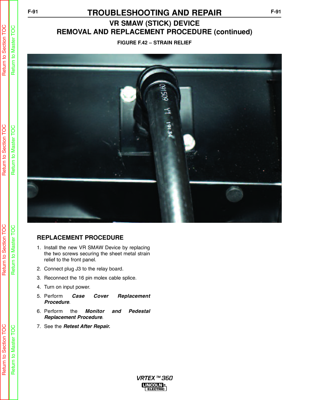
FIGURE F.42 – STRAIN RELIEF
Return to Section TOC Return to Master TOC
Return to Section TOC Return to Master TOC
Return to Section TOC Return to Master TOC
REPLACEMENT PROCEDURE | |||||
1. | Install the new VR SMAW Device by replacing | ||||
| the two screws securing the sheet metal strain | ||||
2. | relief to the front panel. |
| |||
Connect plug J3 to the relay board. | |||||
3. | Reconnect the 16 pin molex cable splice. | ||||
4. | Turn on input power. |
| |||
5. | Perform |
| Case | Cover | Replacement |
6. | rocedure. |
|
|
| |
Perform | the | Monitor | and Pedestal | ||
7. | R placement Procedure. |
| |||
See the | Retest After Repair. |
| |||
VRTEX TM 360
