Return to Section TOC Return to Master TOC
TROUBLESHOOTING AND REPAIR |
DISPLAY BOARD
REMOVAL AND REPLACEMENT PROCEDURE (continued)
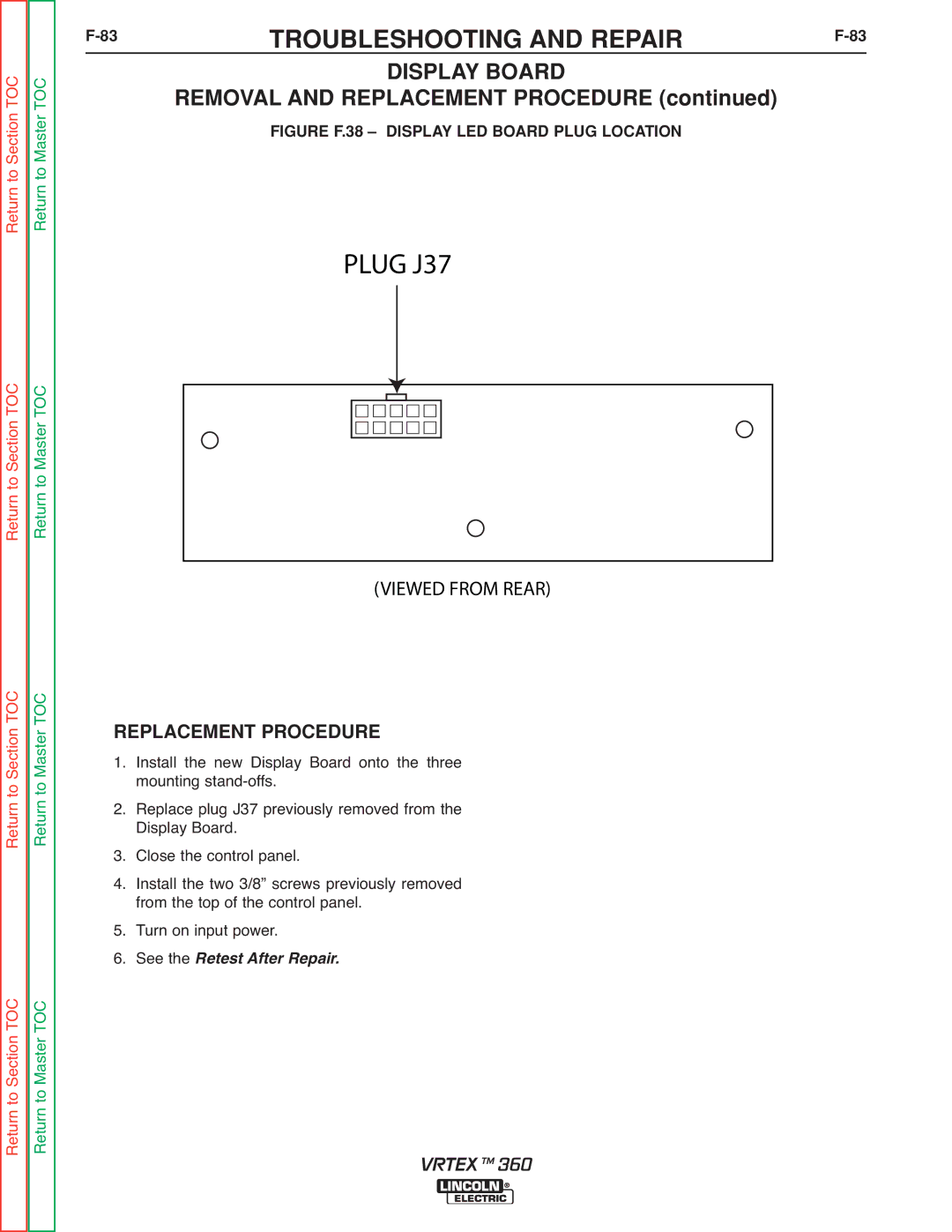
FIGURE F.38 – DISPLAY LED BOARD PLUG LOCATION
PLUG J37
Return to Section TOC Return to Master TOC
Return to Section TOC Return to Master TOC
Return to Section TOC Return to Master TOC
(VIEWED FROM REAR)
REPLACEMENT PROCEDURE
1. Install the new Display Board onto the three mounting
2. Replace plug J37 previously removed from the Display Board.
3. Close the control panel.
4. Install the two 3/8” screws previously removed from the top of the control panel.
5. Turn on input power.
6. See the Retest After Repair.
VRTEX TM 360