Return to Section TOC Return to Master TOC
Return to Section TOC Return to Master TOC
F-37 TROUBLESHOOTING AND REPAIRF-37
POLHEMUS INTERFACE MODULE TEST PROCEDURE (continued)
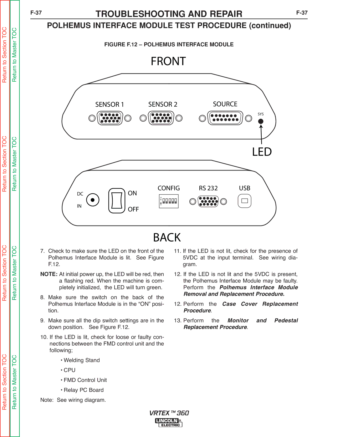
FIGURE F.12 – POLHEMUS INTERFACE MODULE
FRONT
SENSOR 1 | SENSOR 2 | SOURCE |
SYS
LED
CONFIG | RS 232 | USB |
DCON
IN
O
N
OFF
Return to Section TOC Return to Master TOC
Return to Section TOC Return to Master TOC
7. |
| BACK |
|
|
| |
Check to make sure the LED on the front of the | 11. If the LED is not lit, check for the presence of | |||||
| Polhemus Interface Module is lit. See Figure | 5VDC at the input terminal. | See wiring dia- | |||
| F.12. |
| gram. |
|
|
|
NOTE: At initial power up, the LED will be red, then | 12. If the LED is not lit and the 5VDC is present, | |||||
| a flashing red. When the machine is com- | the Polhemus Interface Module may be faulty. | ||||
| pletely initialized, the LED will turn green. | Perform the Polhemus Interface Module | ||||
8. Make sure the | switch on the back of the | R moval and Replacement Procedure. | ||||
| Polhemus Interface Module is in the “ON” posi- | 12. Perform | the | Case Cover Replacement | ||
9. | tion. |
| rocedure. |
|
| |
Make sure all the dip switch settings are in the | 13. Perform | the | Monitor | and Pedestal | ||
| down position. | See Figure F.12. | Replacement Procedure. |
| ||
10. If the LED is lit, check for loose or faulty con- |
|
|
|
| ||
| nections between the FMD control unit and the |
|
|
|
| |
| following; |
|
|
|
|
|
| • Welding Stand |
|
|
|
| |
| • CPU |
|
|
|
|
|
| • FMD Control Unit |
|
|
|
| |
| • Relay PC Board |
|
|
|
| |
Note: See wiring diagram. |
|
|
|
| ||
VRTEX TM 360