Return to Section TOC Return to Master TOC
F-57 TROUBLESHOOTING AND REPAIRF-57
RELAY PC BOARD REMOVAL AND REPLACEMENT PROCEDURE
(continued)
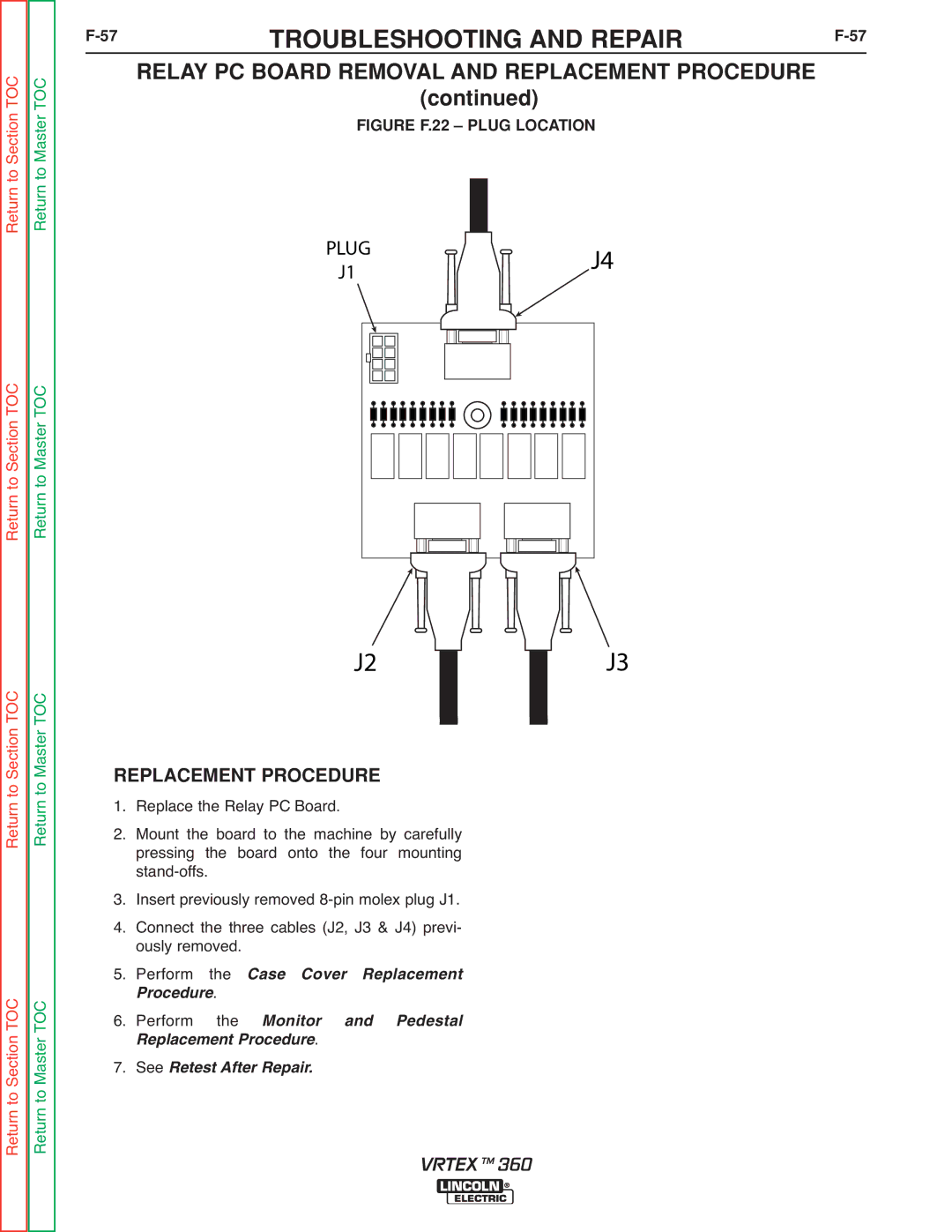
FIGURE F.22 – PLUG LOCATION
PLUG | J4 | |
J1 | ||
|
Return to Section TOC Return to Master TOC
Return to Section TOC Return to Master TOC
Return to Section TOC Return to Master TOC
J2J3
REPLACEMENT PROCEDURE | |||
1. | Replace the Relay PC Board. | ||
2. | Mount the board to the machine by carefully | ||
| pressing the board onto the four mounting | ||
3. |
|
| |
Insert previously removed | |||
4. | Connect the three cables (J2, J3 & J4) previ- | ||
5. | ously removed. | ||
Perform | the | Case Cover Replacement | |
6. | rocedure. |
| |
Perform | the | Monitor and Pedestal | |
7. | R placement Procedure. | ||
See Retest After Repair. | |||
VRTEX TM 360