Return to Section TOC Return to Master TOC
TROUBLESHOOTING AND REPAIR |
DISPLAY BOARD
REMOVAL AND REPLACEMENT PROCEDURE (continued)
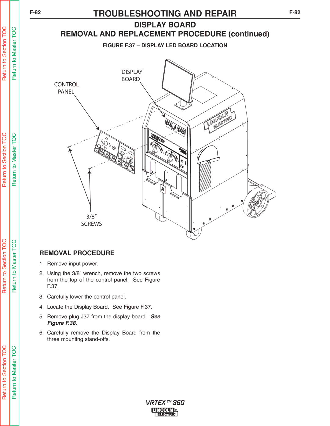
FIGURE F.37 – DISPLAY LED BOARD LOCATION
DISPLAY
BOARD
CONTROL
PANEL
Return to Section TOC Return to Master TOC
Return to Section TOC Return to Master TOC
Return to Section TOC Return to Master TOC
3/8”
SCREWS
REMOVAL PROCEDURE 1. Remove input power.
2. Using the 3/8” wrench, remove the two screws from the top of the control panel. See Figure F.37.
3. Carefully lower the control panel.
4. Locate the Display Board. See Figure F.37.
5. Remove plug J37 from the display board. See
Figure F.38.
6. Carefully remove the Display Board from the three mounting
VRTEX TM 360