Return to Section TOC Return to Master TOC
TROUBLESHOOTING AND REPAIR |
INTERFACE MODULE DIGITAL (USB)
REMOVAL AND REPLACEMENT PROCEDURE (continued)
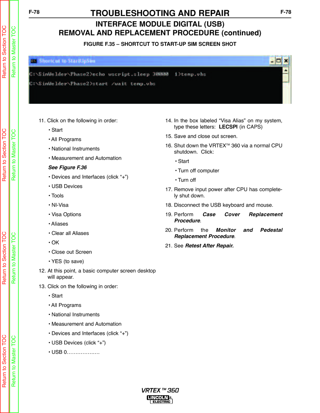
FIGURE F.35 – SHORTCUT TO START-UP SIM SCREEN SHOT
Return to Section TOC Return to Master TOC
Return to Section TOC Return to Master TOC
Return to Section TOC Return to Master TOC
11.Click on the following in order:
•Start
•All Programs
•National Instruments
•Measurement and Automation
•Devices and Interfaces (click “+”)
•USB Devices
•Tools
•
•Visa Options
•Aliases
•Clear all Aliases
•OK
•Close out Screen
•YES (to save)
12.At this point, a basic computer screen desktop will appear.
13.Click on the following in order:
•Start
•All Programs
•National Instruments
•Measurement and Automation
•Devices and Interfaces (click “+”)
•USB Devices (click “+”)
•USB 0……………….See Figure F.36
14.In the box labeled “Visa Alias” on my system, type these letters: LECSPI (in CAPS)
15.Save and close out screen.
16.Shut down the VRTEXTM 360 via a normal CPU shutdown. Click:
•Start
•Turn off computer
•Turn off
17.Remove input power after CPU has complete- ly shut down.
18.Disconnect the USB keyboard and mouse.
19.Perform . Case Cover Replacement
20.Performrocedure the Monitor. and Pedestal SeeR placement Procedure
21.Retest After Repair.
VRTEX TM 360