7.3Installing/Replacing Sanding Belt
1.Machine should be disconnected from power source.
2.Turn the air valve switch (A, Figure 3) to Off position.
3.Remove the lock screw (B, Figure 3) by turning it counterclockwise and lifting up.
4.Remove the spacer block (C, Figure 3).
5.Inspect the sanding belt for defects such as chipped or torn edges. Do not use a belt if it is damaged.
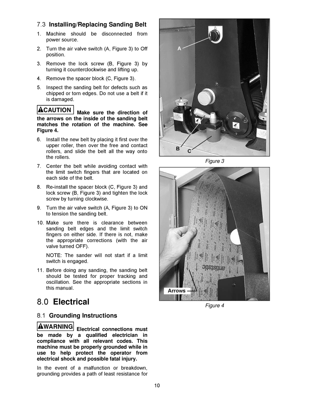
![]() Make sure the direction of the arrows on the inside of the sanding belt matches the rotation of the machine. See Figure 4.
Make sure the direction of the arrows on the inside of the sanding belt matches the rotation of the machine. See Figure 4.
6.Install the new belt by placing it first over the upper roller, then over the free and contact rollers, and slide the belt all the way onto the rollers.
7.Center the belt while avoiding contact with the limit switch fingers that are located on each side of the belt.
8.
9.Turn the air valve switch (A, Figure 3) to ON to tension the sanding belt.
10.Make sure there is clearance between sanding belt edges and the limit switch fingers on either side. If there is not, make the appropriate corrections (with the air valve turned OFF).
NOTE: The sander will not start if a limit switch is engaged.
11.Before doing any sanding, the sanding belt should be tested for proper tracking and oscillation. See the appropriate sections in this manual.
8.0Electrical
8.1Grounding Instructions
![]() Electrical connections must be made by a qualified electrician in compliance with all relevant codes. This machine must be properly grounded while in use to help protect the operator from electrical shock and possible fatal injury.
Electrical connections must be made by a qualified electrician in compliance with all relevant codes. This machine must be properly grounded while in use to help protect the operator from electrical shock and possible fatal injury.
In the event of a malfunction or breakdown, grounding provides a path of least resistance for
Figure 3
Figure 4
10