Latch Time – This is the time that the DVR will before starting a new event (10 seconds to 300 seconds (5 minutes)) after the alarm is ended.
Alarm Out – This will send an alarm signal to up to three connected external alarms when enabled.
Show Message – When this is enabled, an alert message will be displayed on the DVR’s screen.
Alarm Out – To utilize this feature you must connect have at least one external alarm attached to the DVR. You may have up to three separate alarms.
Show Message – When this is enabled, the system will bring up the Alarm Status window whenever an event is detected. You can configure this to display when motion, video loss or masking is detected.
Alarm Upload – The system can upload the alarm to the network including to an alarm monitoring service.
Send
Record Channel – When one camera detects an event, you can set the DVR to activate recording on other cameras.
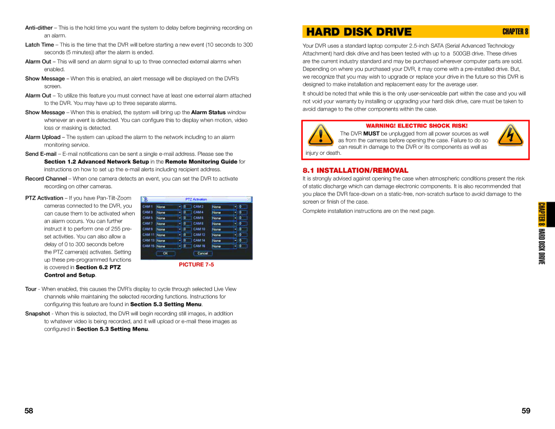
PTZ Activation – If you have
up these
is covered in Section 6.2 PTZPICTURE 7-5 Control and Setup.
Tour - When enabled, this causes the DVR’s display to cycle through selected Live View channels while maintaining the selected recording functions. Instructions for configuring this feature are found in Section 5.3 Setting Menu.
Snapshot - When this is selected, the DVR will begin recording still images, in addition to whatever video is being recorded, and it will upload or
HARD DISK DRIVE | CHAPTER 8 |
Your DVR uses a standard laptop computer
It should be noted that while this is the only
WARNING! ELECTRIC SHOCK RISK!
The DVR MUST be unplugged from all power sources as well
as from the cameras before opening the case. Failure to do so
![]() can result in damage to the DVR or its components as well as injury or death.
can result in damage to the DVR or its components as well as injury or death.
8.1 INSTALLATION/REMOVAL
It is strongly advised against opening the case when atmospheric conditions present the risk of static discharge which can damage electronic components. It is also recommended that you place the DVR
Complete installation instructions are on the next page.
CHAPTER 8 HARD DISK DRIVE
58 | 59 |