Functional Specifications
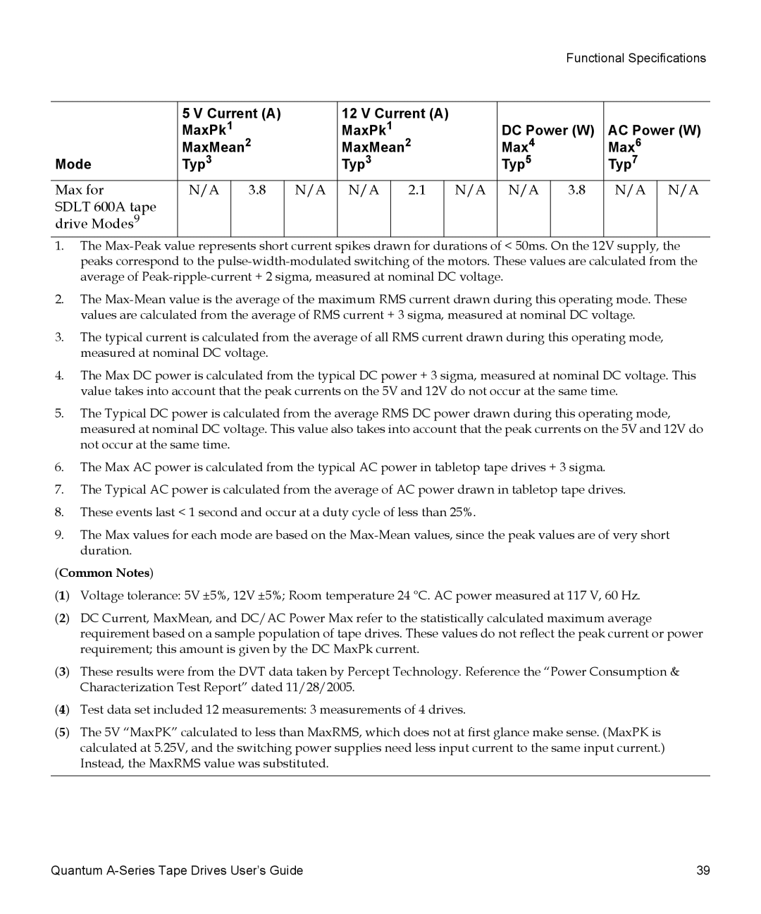
| 5 V Current (A) |
| 12 V Current (A) |
|
|
|
|
| |||
| MaxPk1 |
| MaxPk1 |
| DC Power (W) | AC Power (W) | |||||
| MaxMean2 |
| MaxMean2 |
| Max4 | Max6 | |||||
Mode | Typ3 |
| Typ3 |
| Typ5 | Typ7 | |||||
Max for | N/A | 3.8 | N/A | N/A | 2.1 |
| N/A | N/A | 3.8 | N/A | N/A |
SDLT 600A tape |
|
|
|
|
|
|
|
|
|
|
|
drive Modes9 |
|
|
|
|
|
|
|
|
|
|
|
1.The
2.The
3.The typical current is calculated from the average of all RMS current drawn during this operating mode, measured at nominal DC voltage.
4.The Max DC power is calculated from the typical DC power + 3 sigma, measured at nominal DC voltage. This value takes into account that the peak currents on the 5V and 12V do not occur at the same time.
5.The Typical DC power is calculated from the average RMS DC power drawn during this operating mode, measured at nominal DC voltage. This value also takes into account that the peak currents on the 5V and 12V do not occur at the same time.
6.The Max AC power is calculated from the typical AC power in tabletop tape drives + 3 sigma.
7.The Typical AC power is calculated from the average of AC power drawn in tabletop tape drives.
8.These events last < 1 second and occur at a duty cycle of less than 25%.
9.The Max values for each mode are based on the
(Common Notes)
(1) | Voltage tolerance: 5V ±5%, 12V ±5%; Room temperature 24 °C. AC power measured at 117 V, 60 Hz. |
(2) | DC Current, MaxMean, and DC/AC Power Max refer to the statistically calculated maximum average |
| requirement based on a sample population of tape drives. These values do not reflect the peak current or power |
| requirement; this amount is given by the DC MaxPk current. |
(3) | These results were from the DVT data taken by Percept Technology. Reference the “Power Consumption & |
| Characterization Test Report” dated 11/28/2005. |
(4) | Test data set included 12 measurements: 3 measurements of 4 drives. |
(5) | The 5V “MaxPK” calculated to less than MaxRMS, which does not at first glance make sense. (MaxPK is |
| calculated at 5.25V, and the switching power supplies need less input current to the same input current.) |
| Instead, the MaxRMS value was substituted. |
|
|
Quantum | 39 |