7.2 Structure Diagram
RP-117QD, RP-119QD & RP-120QD
Chapter 7
1
3
2
4
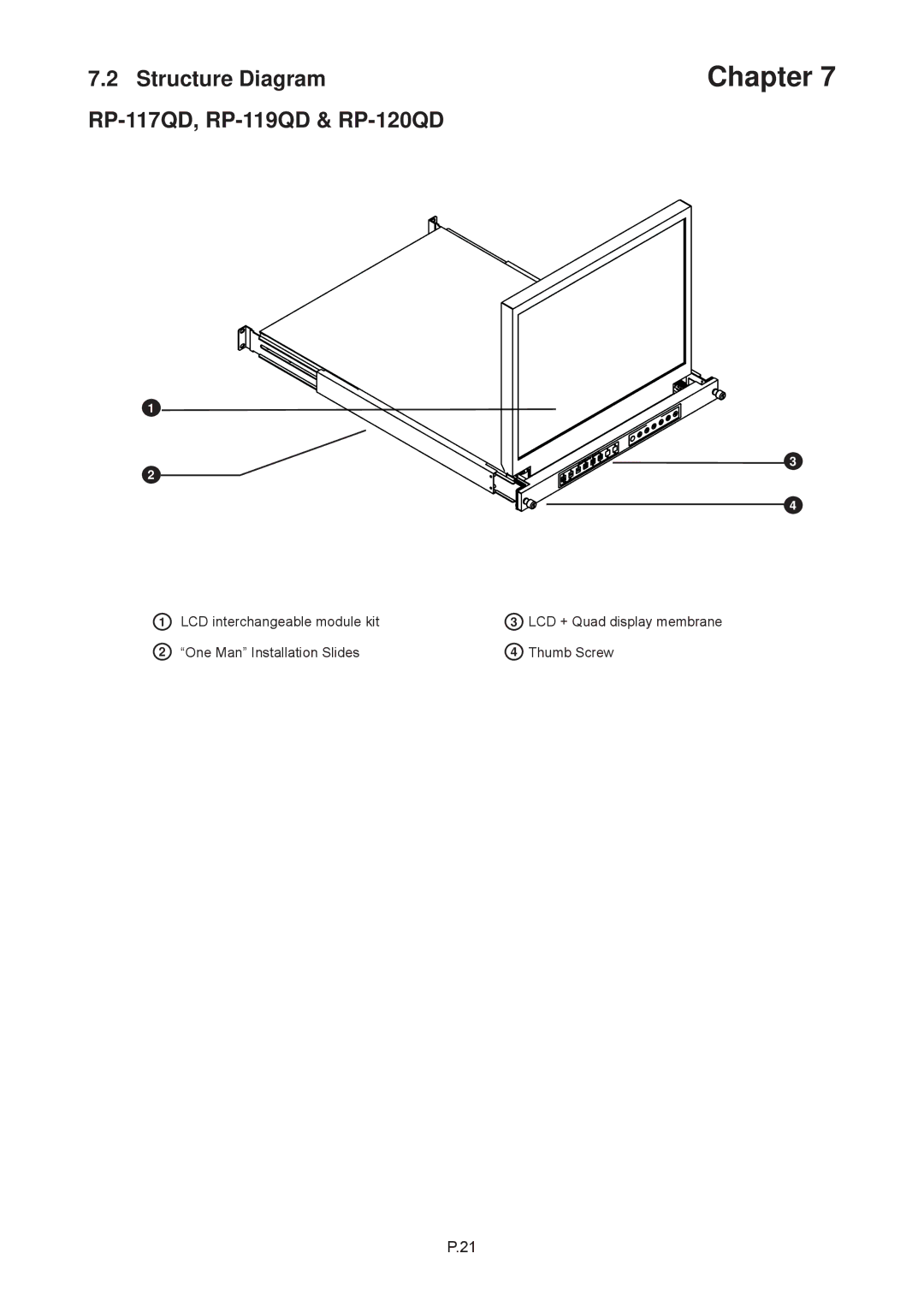
1 | LCD interchangeable module kit | 3 | LCD + Quad display membrane |
2 | “One Man” Installation Slides | 4 | Thumb Screw |
P.21
1
3
2
4
1 | LCD interchangeable module kit | 3 | LCD + Quad display membrane |
2 | “One Man” Installation Slides | 4 | Thumb Screw |
P.21