11.1 Basic System Connection | Chapter 11 |
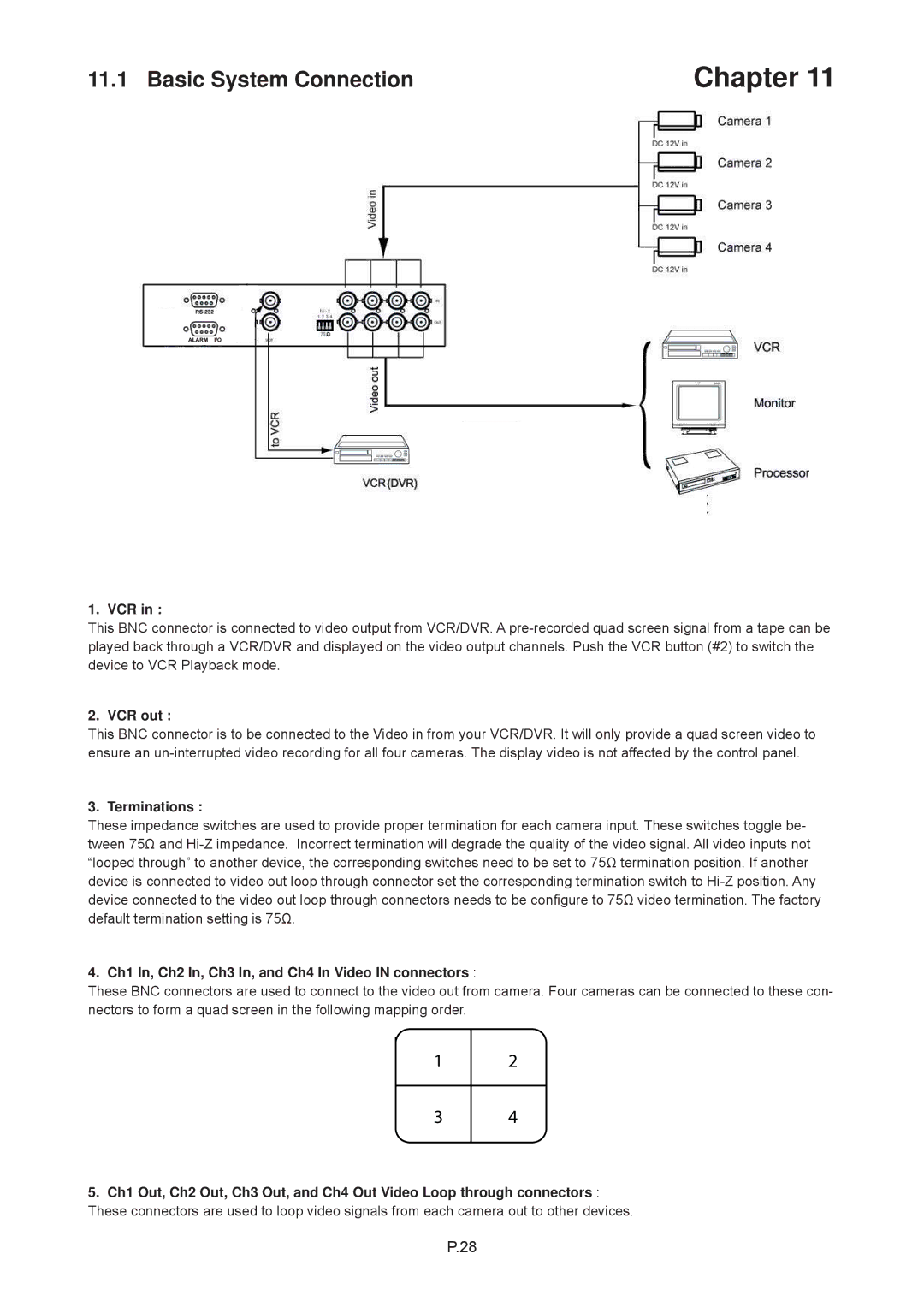
1. VCR in :
This BNC connector is connected to video output from VCR/DVR. A
2. VCR out :
This BNC connector is to be connected to the Video in from your VCR/DVR. It will only provide a quad screen video to ensure an
3. Terminations :
These impedance switches are used to provide proper termination for each camera input. These switches toggle be- tween 75Ω and
4. Ch1 In, Ch2 In, Ch3 In, and Ch4 In Video IN connectors :
These BNC connectors are used to connect to the video out from camera. Four cameras can be connected to these con- nectors to form a quad screen in the following mapping order.
1
2
3
4
5.Ch1 Out, Ch2 Out, Ch3 Out, and Ch4 Out Video Loop through connectors : These connectors are used to loop video signals from each camera out to other devices.
P.28