Page
Widescreen LCD Quad Display
Contents
Chapter 1 Getting Started
Part
Operation
Part 2 43 LCD Quad Display
Chapter 6 RP-817QD, RP-919QD & RP-1020QD
RP-117QD, RP-119QD & RP-120QD
P.41
Blank page
What the warranty does not cover
1.1 Important Safeguards
Chapter
Page
1. Power Cord
1.3 Before Installation
1.5 Optional Accessories
1.4 Unpacking
Matrix DB-15 KVM
1.6 Peripheral Products
Chapter
Matrix Cat6 KVM
User Manu
2.1 Package Contents
RP-W819QD & RP-W922QD
Chapter
Rear view
2.2 Structure Diagram RP-W819QD & RP-W922QD
Front view
Chapter
Chapter
2.3 Installation
RP-W819QD
Install each screws shown in Figure
Installation completed
RP-W922QD
2.3 Installation
Install each screws shown in Figure
Chapter
2.4 Connection RP-W819QD & RP-W922QD
Alarm I/O VCR out
Power
P.10
Package Contents
RP-W119QD
Chapter
LCD interchangeable module kit
3.2 Structure Diagram RP-W119QD
“One Man” Installation Slides
Chapter
P.12
3.3 How to Use the Slides RP-W119QD
Chapter
Chapter
3.4 Connection
Alarm I/O VCR out
Power
DC power input with 12V, 24V, 48V selection
4.1 LCD Specifications RP-W922QD, RP-W819QD & RP-W119QD
Options
Environmental
Net Weight
5.1 Dimensions RP-W922QD, RP-W819QD & RP-W119QD
Product Dimension
Packing Dimension
Chapter
6.1 Package Contents
RP-817QD, RP-919QD & RP-1020QD
Rear view
6.2 Structure Diagram RP-817QD, RP-919QD & RP-1020QD
Chapter
Front view
P.18
6.3 Installation RP-817QD, RP-919QD & RP-1020QD
Install each screws shown in Figure
Chapter
Chapter
6.4 Connection RP-817QD, RP-919QD & RP-1020QD
Alarm I/O VCR out
Power
P.20
RP-117QD, RP-119QD & RP-120QD
Package Contents
Chapter
LCD interchangeable module kit
7.2 Structure Diagram RP-117QD, RP-119QD & RP-120QD
“One Man” Installation Slides
Chapter
Caution Keep your fingers away from the slide stop
7.3 How to Use the Slides RP-117QD, RP-119QD & RP-120QD
Chapter
P.22
Chapter
7.4 Connection
Alarm I/O VCR out
Power
Chapter
LCD Specifications
RP-817QD, RP-919QD, RP-1020QD, RP-117QD, RP-119QD & RP-120QD
DC power input with 12V, 24V, 48V selection
Net Weight
9.1 Dimensions
Product Dimension
Packing Dimension
Power light Green = On Orange = Power saving Power on / off LCD
10.1 On-screen Display Operation
For LCD OSD Menu
For Quad Display Control
Image
10.2 On-screen Menu
OSD Configuration Page
Chapter
1. VCR in
11.1 Basic System Connection
4. Ch1 In, Ch2 In, Ch3 In, and Ch4 In Video IN connectors
Chapter
P.29
11.2 ALARM I/O Connection & Operation
1. ALARM I/O
Chapter
Chapter
11.2 ALARM I/O Connection & Operation
3 Sensor Activated Alarm
4 Video Loss Alarm
ALARM
11.3 Remote Control Connection & Operation
Chapter
RS-232 Cable Wire
1 2 3 4 6 7 8
11.3 Remote Control Connection & Operation
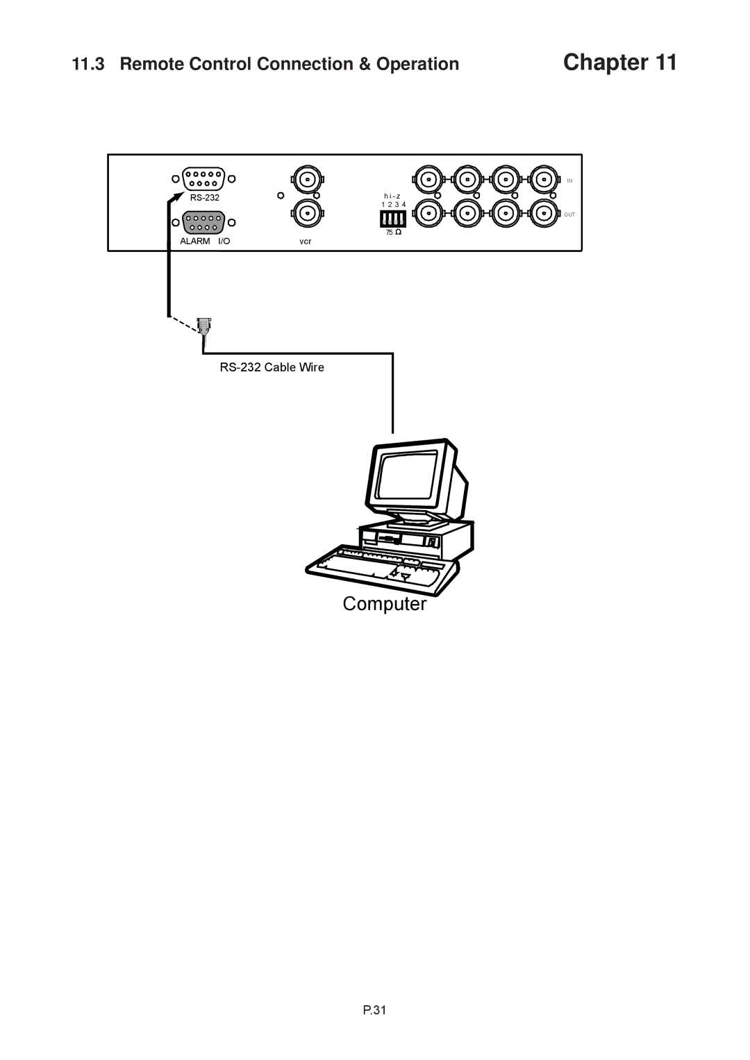
1. Pin assignment of the male type 9 pin D-sub connector
Chapter
Buzzer & Security lock ON Stop
11.3 Remote Control Connection & Operation
Chapter
VCR mode
11.3 Remote Control Connection & Operation
Display Mode
Auto-sequencing mode
Chapter
11.3 Remote Control Connection & Operation
b7 - b4 Sensor Activated Alarm
Quad Display Control
11.4 Quad Display Operation
Setup buttons #1, #2
Chapter
P.37
11.5 Quad Display On-screen Menu
Chapter
P.38
Chapter
11.5 Quad Display On-screen Menu
STATUS
7. The Still Frame Display Mode
11.5 Quad Display On-screen Menu
5. The Quad Display Mode
6. The Full Screen Display Mode
Description
11.6 VCR Operations
11.7 Quad Display Specifications
Chapter
Chapter
12.1 DC Power Options
RP-W119QD & RP-120QD
RP-W819QD & RP-W922QD RP-817QD, RP-919QD & RP-1020QD
Chapter
13.1 Troubleshooting
1. How do I adjust the resolution?
3. The membrane power light is not ON
Blank page
CV-QD34-0109V1