11.3 Remote Control Connection & Operation | Chapter 11 |
The device may be controlled via the male type 9 pin
Note: Please power off the unit before connecting the Remote Control keypad.
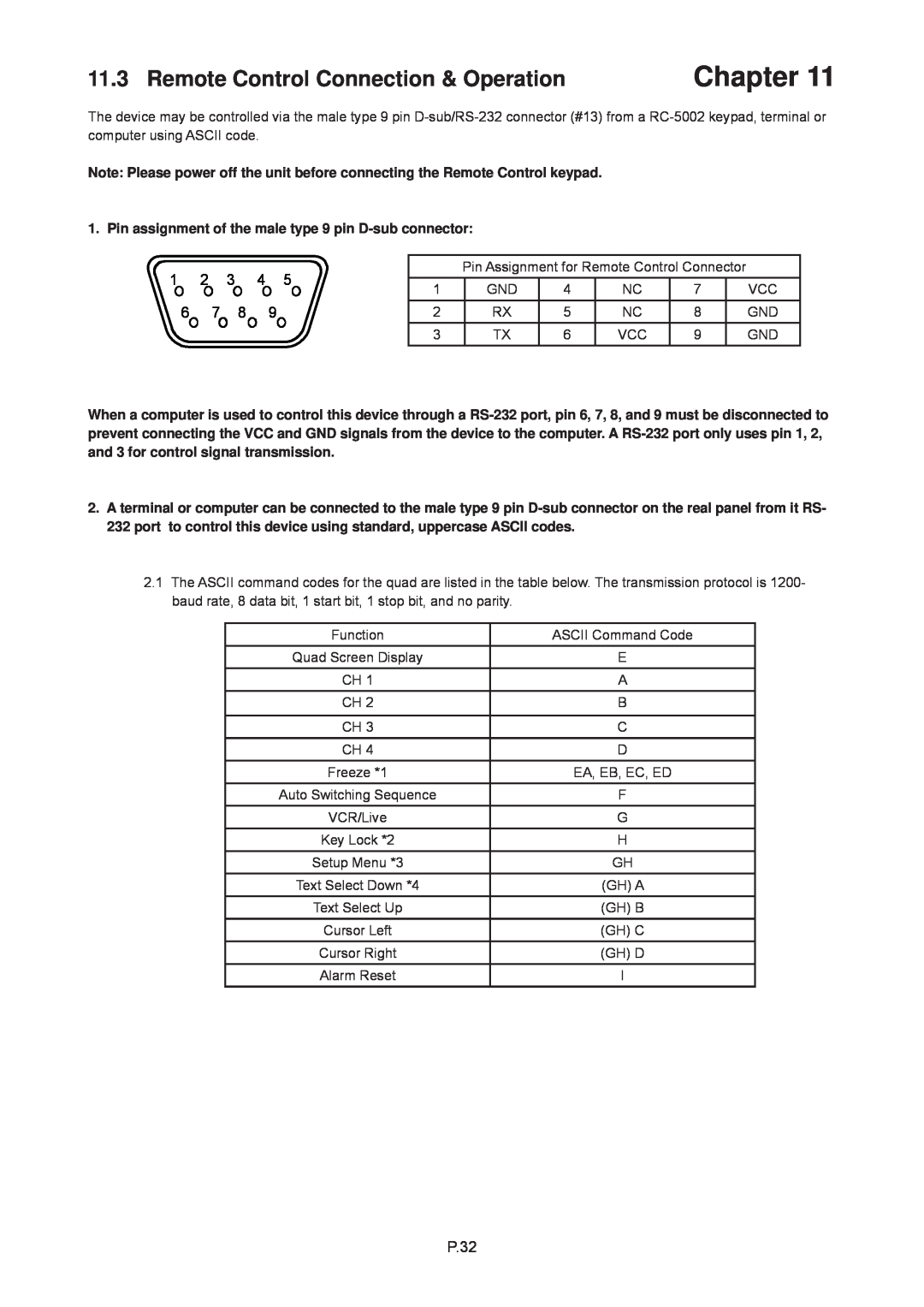
1. Pin assignment of the male type 9 pin D-sub connector:
1 2 3 4 5
6 7 8 9
Pin Assignment for Remote Control Connector
1 | GND | 4 | NC | 7 | VCC |
2 | RX | 5 | NC | 8 | GND |
3 | TX | 6 | VCC | 9 | GND |
When a computer is used to control this device through a
2.A terminal or computer can be connected to the male type 9 pin
2.1The ASCII command codes for the quad are listed in the table below. The transmission protocol is 1200- baud rate, 8 data bit, 1 start bit, 1 stop bit, and no parity.
Function | ASCII Command Code |
Quad Screen Display | E |
CH 1 | A |
CH 2 | B |
|
|
CH 3 | C |
CH 4 | D |
Freeze *1 | EA, EB, EC, ED |
Auto Switching Sequence | F |
VCR/Live | G |
Key Lock *2 | H |
Setup Menu *3 | GH |
Text Select Down *4 | (GH) A |
Text Select Up | (GH) B |
Cursor Left | (GH) C |
Cursor Right | (GH) D |
Alarm Reset | I |