Page
Part
Contents
Chapter 1 Getting Started
Widescreen LCD Quad Display
RP-117QD, RP-119QD & RP-120QD
Part 2 43 LCD Quad Display
Chapter 6 RP-817QD, RP-919QD & RP-1020QD
Operation
Blank page
P.41
1.1 Important Safeguards
Chapter
What the warranty does not cover
Page
1.4 Unpacking
1.3 Before Installation
1.5 Optional Accessories
1. Power Cord
Matrix Cat6 KVM
1.6 Peripheral Products
Chapter
Matrix DB-15 KVM
Chapter
2.1 Package Contents
RP-W819QD & RP-W922QD
User Manu
Chapter
2.2 Structure Diagram RP-W819QD & RP-W922QD
Front view
Rear view
Install each screws shown in Figure
2.3 Installation
RP-W819QD
Chapter
Install each screws shown in Figure
RP-W922QD
2.3 Installation
Installation completed
Power
2.4 Connection RP-W819QD & RP-W922QD
Alarm I/O VCR out
Chapter
Chapter
Package Contents
RP-W119QD
P.10
Chapter
3.2 Structure Diagram RP-W119QD
“One Man” Installation Slides
LCD interchangeable module kit
3.3 How to Use the Slides RP-W119QD
Chapter
P.12
Power
3.4 Connection
Alarm I/O VCR out
Chapter
Environmental
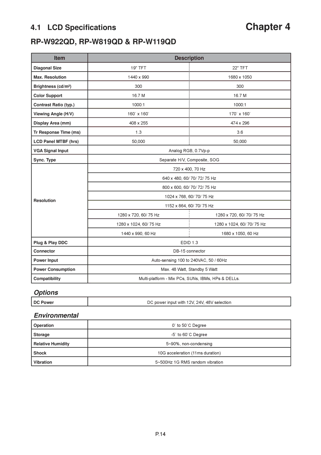
4.1 LCD Specifications RP-W922QD, RP-W819QD & RP-W119QD
Options
DC power input with 12V, 24V, 48V selection
Packing Dimension
5.1 Dimensions RP-W922QD, RP-W819QD & RP-W119QD
Product Dimension
Net Weight
6.1 Package Contents
RP-817QD, RP-919QD & RP-1020QD
Chapter
Front view
6.2 Structure Diagram RP-817QD, RP-919QD & RP-1020QD
Chapter
Rear view
Chapter
6.3 Installation RP-817QD, RP-919QD & RP-1020QD
Install each screws shown in Figure
P.18
Power
6.4 Connection RP-817QD, RP-919QD & RP-1020QD
Alarm I/O VCR out
Chapter
Chapter
RP-117QD, RP-119QD & RP-120QD
Package Contents
P.20
Chapter
7.2 Structure Diagram RP-117QD, RP-119QD & RP-120QD
“One Man” Installation Slides
LCD interchangeable module kit
P.22
7.3 How to Use the Slides RP-117QD, RP-119QD & RP-120QD
Chapter
Caution Keep your fingers away from the slide stop
Power
7.4 Connection
Alarm I/O VCR out
Chapter
DC power input with 12V, 24V, 48V selection
LCD Specifications
RP-817QD, RP-919QD, RP-1020QD, RP-117QD, RP-119QD & RP-120QD
Chapter
Packing Dimension
9.1 Dimensions
Product Dimension
Net Weight
For Quad Display Control
10.1 On-screen Display Operation
For LCD OSD Menu
Power light Green = On Orange = Power saving Power on / off LCD
Chapter
10.2 On-screen Menu
OSD Configuration Page
Image
Chapter
11.1 Basic System Connection
4. Ch1 In, Ch2 In, Ch3 In, and Ch4 In Video IN connectors
1. VCR in
Chapter
11.2 ALARM I/O Connection & Operation
1. ALARM I/O
P.29
4 Video Loss Alarm
11.2 ALARM I/O Connection & Operation
3 Sensor Activated Alarm
Chapter
RS-232 Cable Wire
11.3 Remote Control Connection & Operation
Chapter
ALARM
Chapter
11.3 Remote Control Connection & Operation
1. Pin assignment of the male type 9 pin D-sub connector
1 2 3 4 6 7 8
11.3 Remote Control Connection & Operation
Chapter
Buzzer & Security lock ON Stop
Auto-sequencing mode
11.3 Remote Control Connection & Operation
Display Mode
VCR mode
11.3 Remote Control Connection & Operation
b7 - b4 Sensor Activated Alarm
Chapter
Chapter
11.4 Quad Display Operation
Setup buttons #1, #2
Quad Display Control
11.5 Quad Display On-screen Menu
Chapter
P.37
STATUS
Chapter
11.5 Quad Display On-screen Menu
P.38
6. The Full Screen Display Mode
11.5 Quad Display On-screen Menu
5. The Quad Display Mode
7. The Still Frame Display Mode
Chapter
11.6 VCR Operations
11.7 Quad Display Specifications
Description
RP-W819QD & RP-W922QD RP-817QD, RP-919QD & RP-1020QD
12.1 DC Power Options
RP-W119QD & RP-120QD
Chapter
3. The membrane power light is not ON
13.1 Troubleshooting
1. How do I adjust the resolution?
Chapter
Blank page
CV-QD34-0109V1