4. OPERATION
FRONT PANELS
The operation of the UPS depends on which front panel is used. The following section explains the operation for the LED and the LCD front panels.
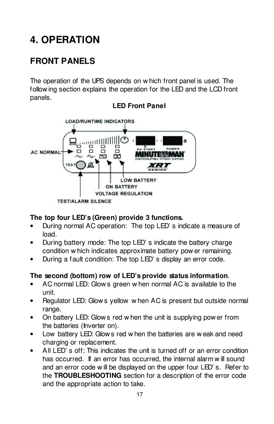
LED Front Panel
The top four LED’s (Green) provide 3 functions.
∙During normal AC operation: The top LED’s indicate a measure of load.
∙During battery mode: The top LED’s indicate the battery charge condition which indicates approximate battery power remaining.
∙During a fault condition: The top LED’s display an error code.
The second (bottom) row of LED’s provide status information.
∙AC normal LED: Glows green when normal AC is available to the unit.
∙Regulator LED: Glows yellow when AC is present but outside normal range.
∙On battery LED: Glows red when the unit is supplying power from the batteries (Inverter on).
∙Low battery LED: Glows red when the batteries are weak and need charging or replacement.
∙All LED’s off: This indicates the unit is turned off or an error condition has occurred. If an error has occurred, the internal alarm will sound and an error code will be displayed on the upper four LED’s. Refer to the TROUBLESHOOTING section for a description of the error code and the appropriate action to take.
17