INSTALLATION, STEP BY STEP
1.Insure UPS Power switch is OFF. Place the optional XRTBP battery pack(s), if used, and XRT UPS in its final location.
2.When installing the XRT1000 and above UPS’s or the XRT600 with optional battery pack(s):
a)Remove the self stick protective strip from the rear of the XRT600 (not required on XRT1000 , 1500, and 2000), and from the optional battery pack cable.
b)Loosen the retainer screws on the rear of the UPS and drop the retainer bracket down.
c)Plug the battery pack cable connector into the XRT remote battery pack connector insuring connections mate RED to RED and BLACK to BLACK. Push the retaining bracket “up” to secure the battery connector in place and
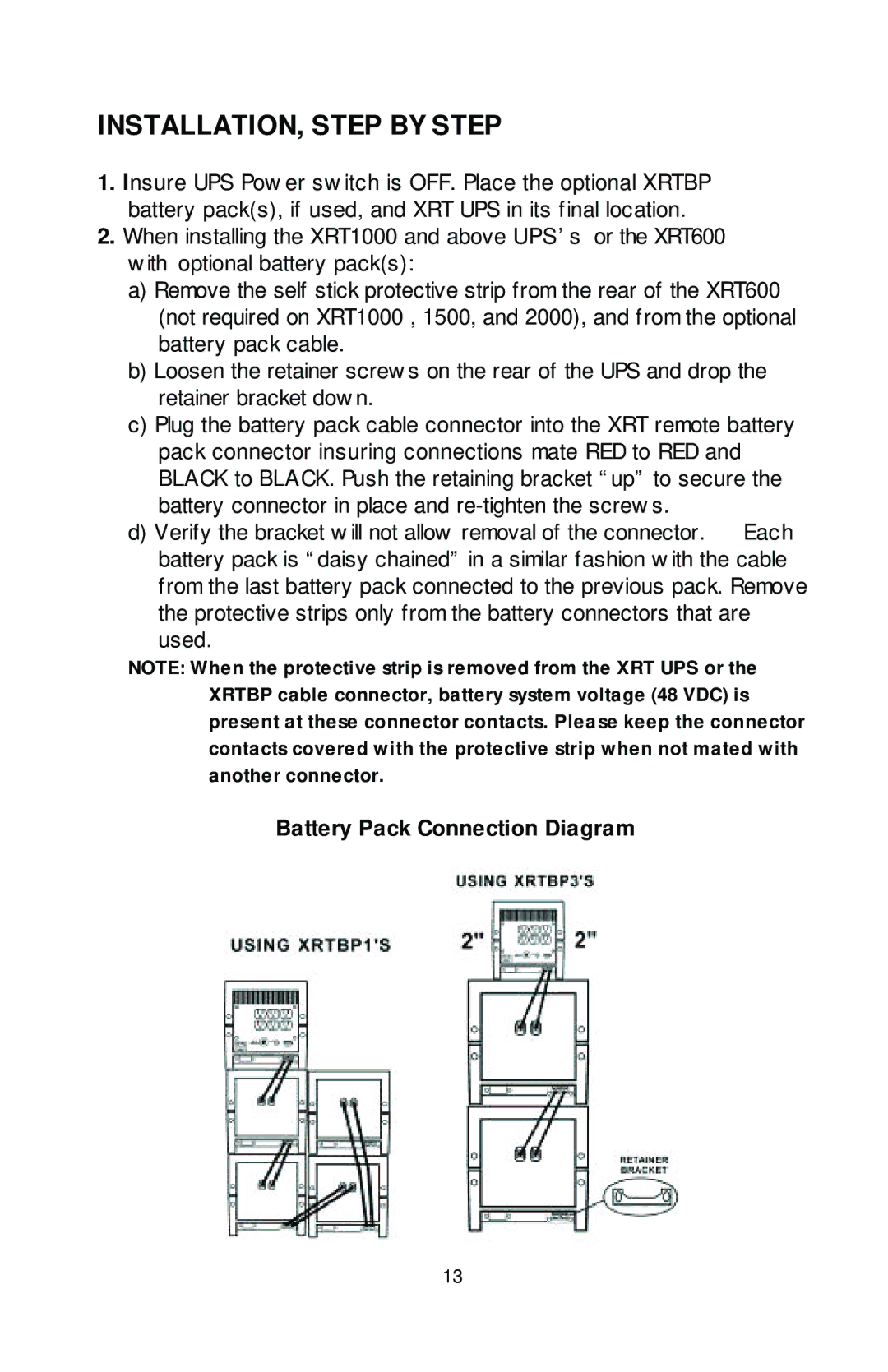
d) Verify the bracket will not allow removal of the connector. Each battery pack is “daisy chained” in a similar fashion with the cable from the last battery pack connected to the previous pack. Remove the protective strips only from the battery connectors that are used.
NOTE: When the protective strip is removed from the XRT UPS or the XRTBP cable connector, battery system voltage (48 VDC) is present at these connector contacts. Please keep the connector contacts covered with the protective strip when not mated with another connector.
Battery Pack Connection Diagram
13