24 | Pathfinder Radar Scanners |
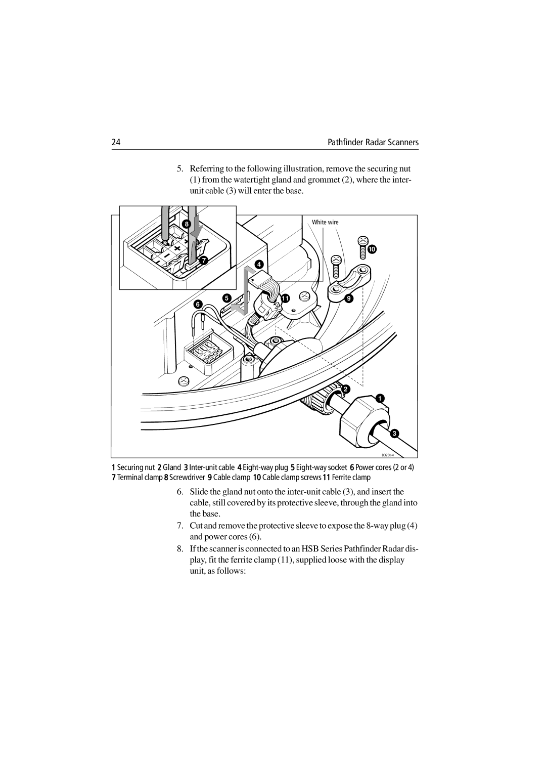
5.Referring to the following illustration, remove the securing nut
(1) from the watertight gland and grommet (2), where the inter- unit cable (3) will enter the base.
8 |
| White wire |
|
| 10 |
7 | 4 |
|
|
| |
5 | 11 | 9 |
6 |
|
|
![]() 2
2
1
3
1 Securing nut 2 Gland 3
6.Slide the gland nut onto the
7.Cut and remove the protective sleeve to expose the
8.If the scanner is connected to an HSB Series Pathfinder Radar dis- play, fit the ferrite clamp (11), supplied loose with the display unit, as follows: