32 | Pathfinder Radar Scanners |
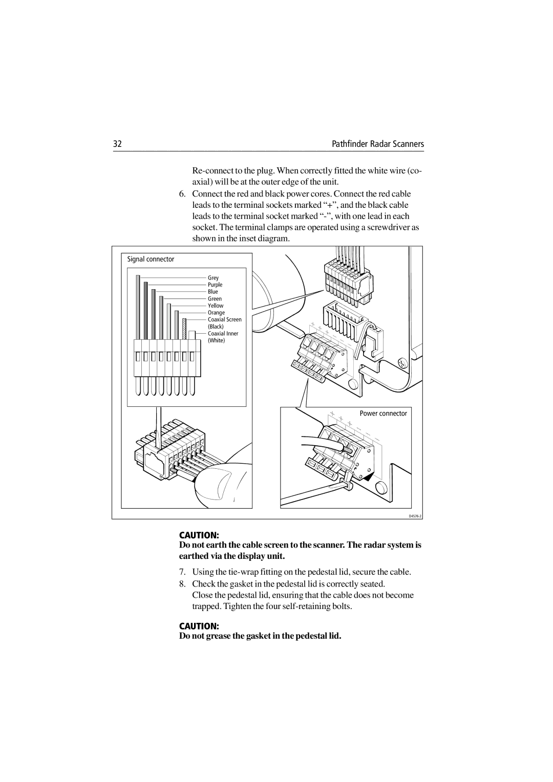
6.Connect the red and black power cores. Connect the red cable leads to the terminal sockets marked “+”, and the black cable leads to the terminal socket marked
Signal connector
Grey
Purple
Blue Green
Yellow
Orange
![]()
![]() Coaxial Screen
Coaxial Screen
(Black)
Coaxial Inner (White)
Power connector
CAUTION:
Do not earth the cable screen to the scanner. The radar system is earthed via the display unit.
7.Using the
8.Check the gasket in the pedestal lid is correctly seated.
Close the pedestal lid, ensuring that the cable does not become trapped. Tighten the four
CAUTION: