Chapter 2: Installing the Scanner | 31 |
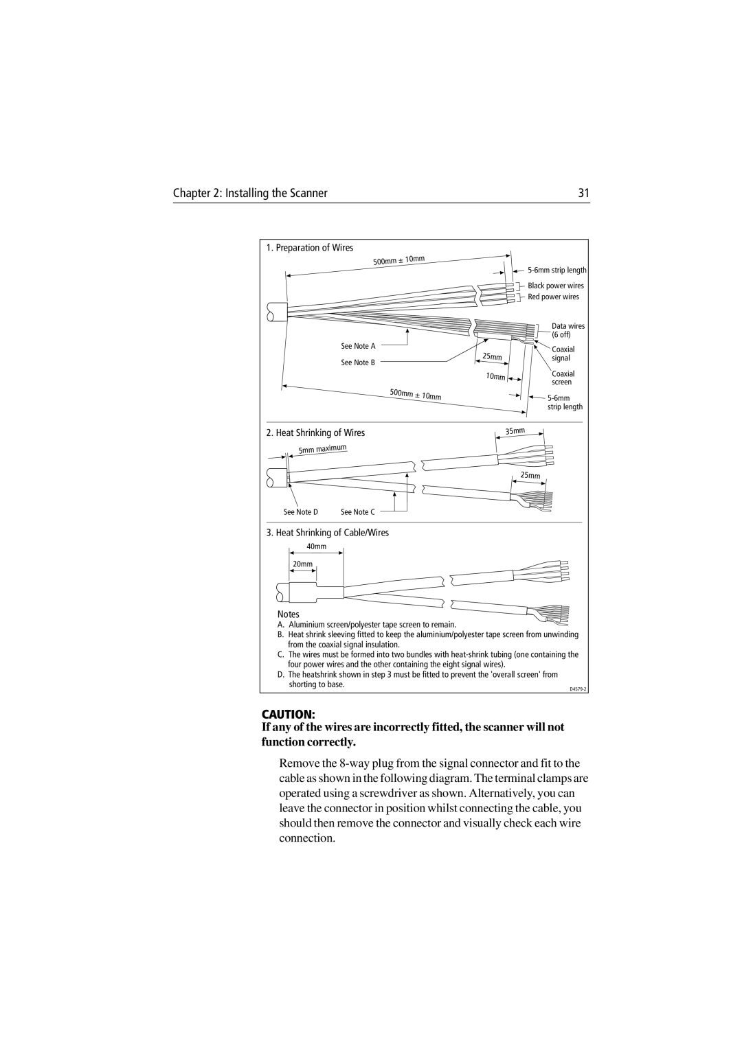
1. Preparation of Wires
500mm | ± 10mm |
|
See Note A
See Note B
500mm ± 10mm
| ||
| Black power wires | |
| Red power wires | |
| Data wires | |
| (6 off) | |
25mm | Coaxial | |
signal | ||
10mm | Coaxial | |
screen | ||
|
![]()
2. Heat Shrinking of Wires
5mm | maximum |
|
See Note D | See Note C |
35mm
25mm
3. Heat Shrinking of Cable/Wires
40mm
20mm
Notes
A. Aluminium screen/polyester tape screen to remain.
B. Heat shrink sleeving fitted to keep the aluminium/polyester tape screen from unwinding from the coaxial signal insulation.
C. The wires must be formed into two bundles with
D. The heatshrink shown in step 3 must be fitted to prevent the 'overall screen' from shorting to base.
CAUTION:
If any of the wires are incorrectly fitted, the scanner will not function correctly.
Remove the