1005 specifications
Raypak is a prominent name in the heating industry, known for its innovative and efficient heating solutions for residential and commercial applications. The models 2005, 1005, and 1505 are notable offerings from Raypak, each designed to provide reliable performance, energy efficiency, and user-friendly operation.The Raypak 2005 model stands out for its robust construction and high efficiency. It utilizes advanced technology to ensure consistent heating and reliability. With a high-capacity output, the 2005 is ideal for larger pools and spa applications, efficiently maintaining desired temperatures even during colder months. Its digital control system allows for precise temperature settings, enabling users to customize their heating needs effectively.
The 1005 model is an excellent choice for medium-sized pools and spas, offering a perfect balance of power and energy efficiency. One of its key features is the ability to operate quietly, making it suitable for residential areas where noise can be a concern. The 1005 employs a reliable gas burning system that maximizes fuel efficiency and provides fast heating. Its compact design also makes it easy to install, saving space while delivering exceptional performance.
The Raypak 1505 model is designed for versatility, catering to a wide range of heating requirements. One of its standout characteristics is its corrosion-resistant heat exchanger, which ensures long-lasting performance even in harsh environments. The 1505 also incorporates a user-friendly digital interface, allowing for easy operation and monitoring of temperature settings. It supports both natural gas and propane, providing flexibility to users based on their energy source preferences.
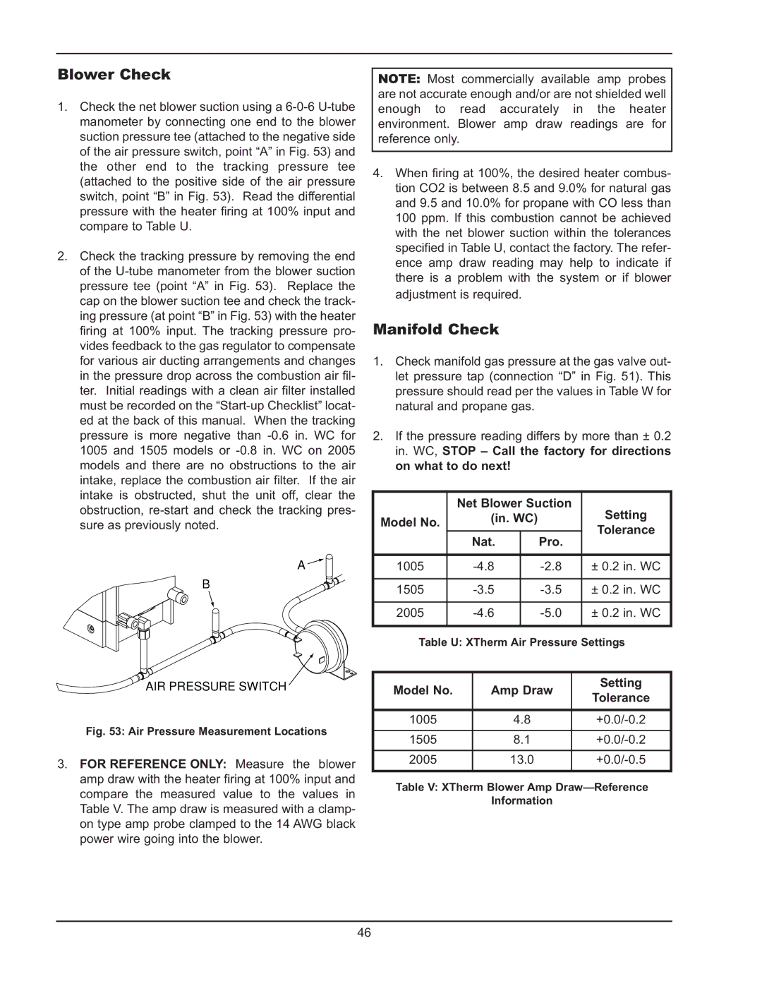
All three models—the 2005, 1005, and 1505—benefit from Raypak's commitment to energy efficiency. They are designed to meet stringent environmental standards while minimizing operational costs for the user. Additionally, their reliable safety features, such as pressure switches and safety valves, ensure safe operation across various conditions.
In summary, Raypak's 2005, 1005, and 1505 models exhibit a combination of efficiency, durability, and user-friendliness. With their advanced technologies and adaptable designs, these heaters are suitable for a wide array of heating applications, providing users with reliable solutions for their heating needs. Whether for residential or commercial use, Raypak's commitment to quality and innovation makes these models excellent choices for anyone seeking dependable heating solutions.

