Connections & Setup
Explanation of Jacks
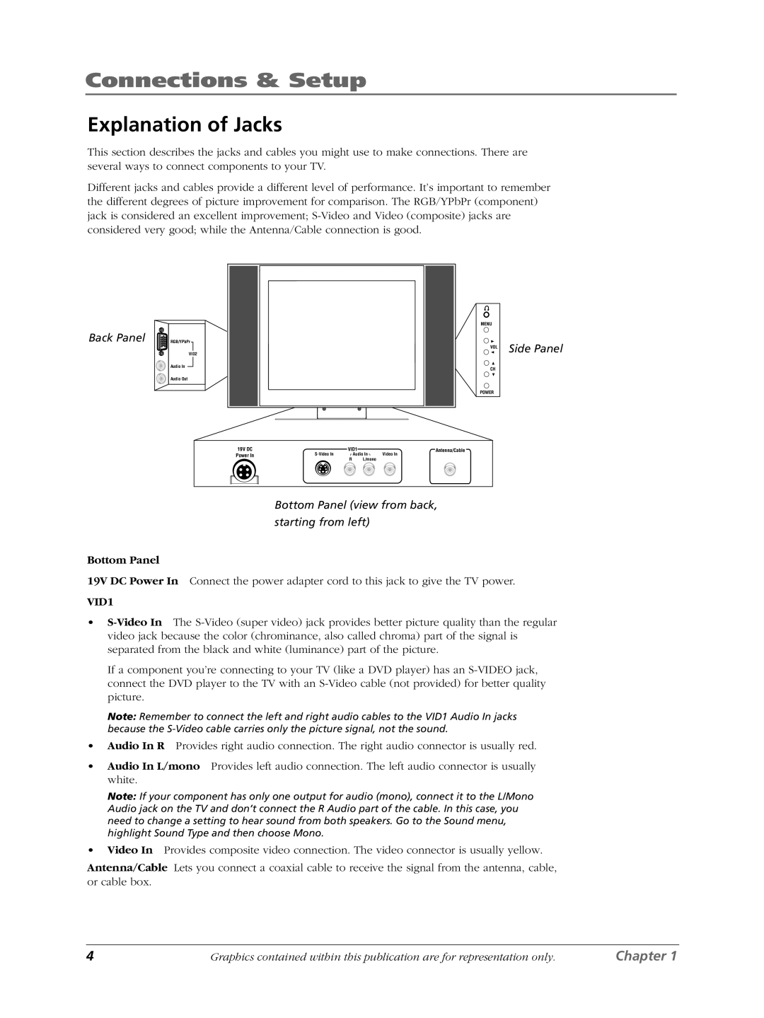
This section describes the jacks and cables you might use to make connections. There are several ways to connect components to your TV.
Different jacks and cables provide a different level of performance. It’s important to remember the different degrees of picture improvement for comparison. The RGB/YPbPr (component) jack is considered an excellent improvement;
Back Panel | RGB/YPbPr |
VID2
Audio In
Audio Out
19V DC
Power In
MENU
VOL Side Panel
CH
POWER
VID1 | Antenna/Cable | |
Audio In | Video In |
RL/mono
Bottom Panel (view from back,
starting from left)
Bottom Panel
19V DC Power In Connect the power adapter cord to this jack to give the TV power.
VID1
•
If a component you’re connecting to your TV (like a DVD player) has an
Note: Remember to connect the left and right audio cables to the VID1 Audio In jacks because the
•Audio In R Provides right audio connection. The right audio connector is usually red.
•Audio In L/mono Provides left audio connection. The left audio connector is usually white.
Note: If your component has only one output for audio (mono), connect it to the L/Mono Audio jack on the TV and don’t connect the R Audio part of the cable. In this case, you need to change a setting to hear sound from both speakers. Go to the Sound menu, highlight Sound Type and then choose Mono.
•Video In Provides composite video connection. The video connector is usually yellow.
Antenna/Cable Lets you connect a coaxial cable to receive the signal from the antenna, cable, or cable box.
4 | Graphics contained within this publication are for representation only. | Chapter 1 |
