Connections & Setup
TV
ANT IN
TV
RF MODULATOR | 3 |
RF | Modulator |
|
CABLE
OR
ANT IN | AUDIO | VIDEO |
| IN | IN |
| TO TV |
|
|
|
|
| 1 |
|
| 2 |
| DVD |
|
|
|
|
| |
|
|
|
|
|
|
| |
| PLAYER | SUBWOOFER | CENTER |
|
| COMPOSITE | |
|
|
|
| 1 | Y | Y |
|
| OPTICAL | COAX. |
| 2 | Pb | Pb |
|
|
|
|
|
|
| ||
|
| Pb |
| FRONT |
|
|
|
|
|
|
| MIXED |
|
|
|
|
| R |
| L | Pr | Pr |
|
|
|
| COMPONENT | PROG. SCAN | |||
| DIGITAL |
|
|
| |||
DVD |
| 5.1 CHANNEL | VIDEO OUT |
| |||
AUDIO OUT |
| AUDIO OUT |
| ||||
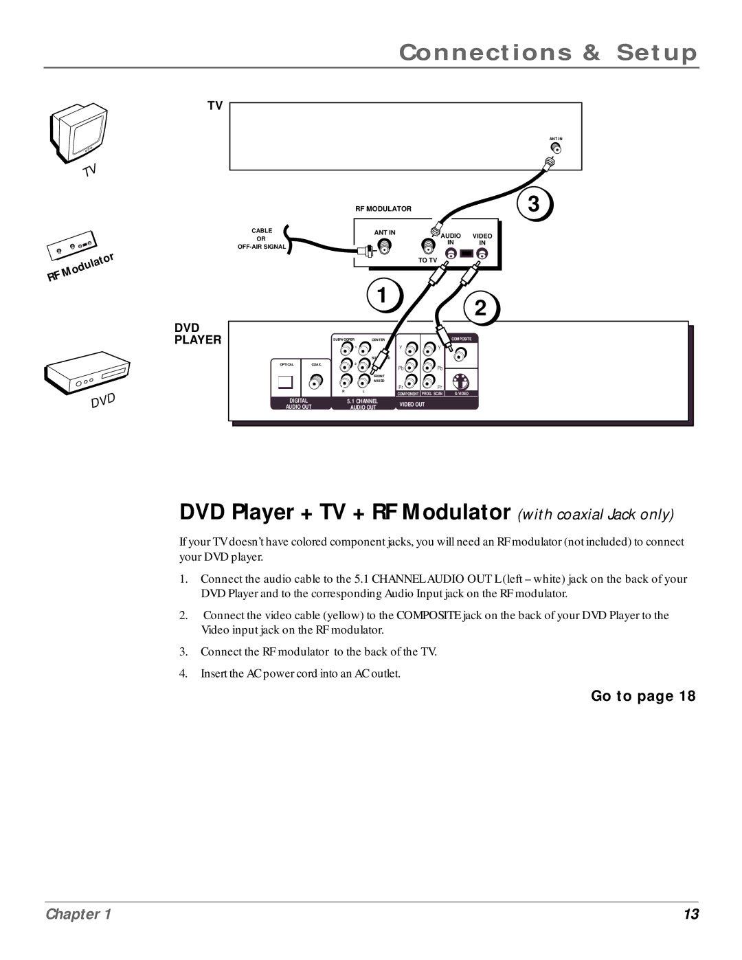
DVD Player + TV + RF Modulator (with coaxial Jack only)
If your TV doesn’t have colored component jacks, you will need an RF modulator (not included) to connect your DVD player.
1.Connect the audio cable to the 5.1 CHANNEL AUDIO OUT L (left – white) jack on the back of your DVD Player and to the corresponding Audio Input jack on the RF modulator.
2.Connect the video cable (yellow) to the COMPOSITE jack on the back of your DVD Player to the Video input jack on the RF modulator.
3.Connect the RF modulator to the back of the TV.
4.Insert the AC power cord into an AC outlet.
Go to page 18
Chapter 1 | 13 |
