Connections & Setup
Position
Cable Box
VCR |
Cable Box |
Box
Cable
From Cable
Line Feed
CABLE BOX | 3 |
| |
IN FROM ANT |
|
OUT TO TV | CH3 |
CH4 |
Transmitter |
VCR's |
Signal |
VCR
2
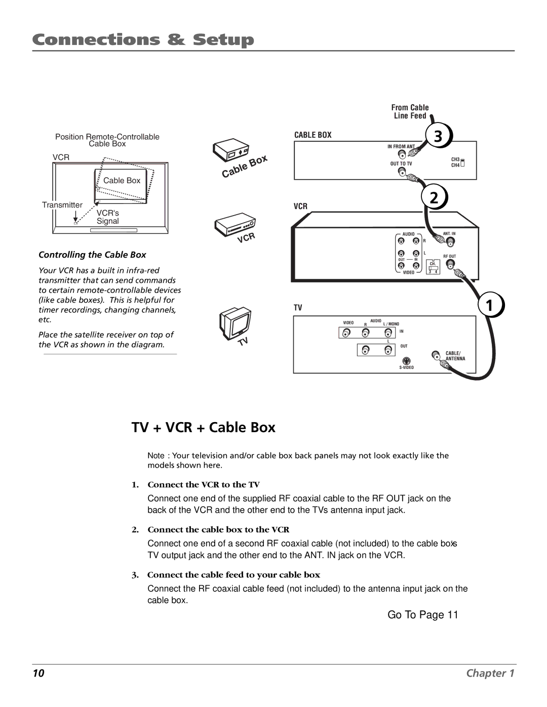
Controlling the Cable Box
Your VCR has a built in
Place the satellite receiver on top of the VCR as shown in the diagram.
VCR
TV
AUDIO | ANT. IN | ||
|
| R | |
|
| L | |
OUT | IN | RF OUT | |
CH. | |||
|
| ||
VIDEO |
| 3 4 | |
TV |
| 1 | |
VIDEO |
| AUDIO | |
R | L / MONO | ||
| |||
|
| IN | |
|
| L | |
|
| OUT | |
|
| CABLE/ | |
|
| ANTENNA | |
|
|
TV + VCR + Cable Box
Note: Your television and/or cable box back panels may not look exactly like the models shown here.
1.Connect the VCR to the TV
Connect one end of the supplied RF coaxial cable to the RF OUT jack on the back of the VCR and the other end to the TV’s antenna input jack.
2.Connect the cable box to the VCR
Connect one end of a second RF coaxial cable (not included) to the cable box’s TV output jack and the other end to the ANT. IN jack on the VCR.
3.Connect the cable feed to your cable box
Connect the RF coaxial cable feed (not included) to the antenna input jack on the cable box.
Go To Page 11
10 | Chapter 1 |
