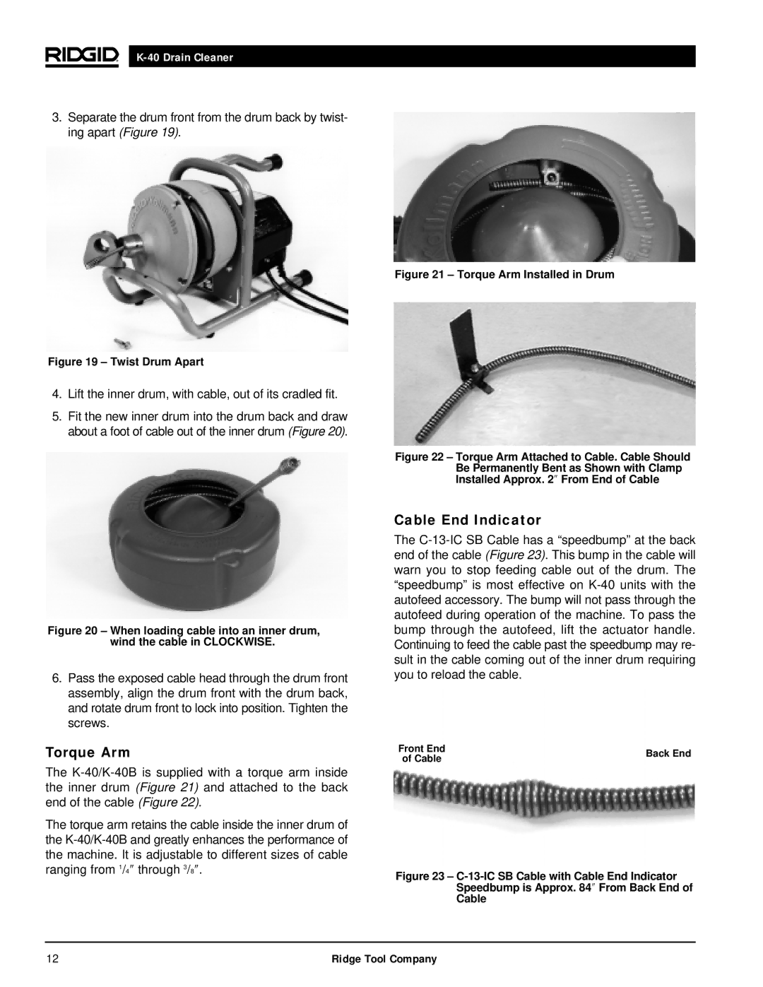
3.Separate the drum front from the drum back by twist- ing apart (Figure 19).
Figure 19 – Twist Drum Apart
4.Lift the inner drum, with cable, out of its cradled fit.
5.Fit the new inner drum into the drum back and draw about a foot of cable out of the inner drum (Figure 20).
Figure 20 – When loading cable into an inner drum, wind the cable in CLOCKWISE.
6.Pass the exposed cable head through the drum front assembly, align the drum front with the drum back, and rotate drum front to lock into position. Tighten the screws.
Torque Arm
The
The torque arm retains the cable inside the inner drum of the
Figure 21 – Torque Arm Installed in Drum
Figure 22 – Torque Arm Attached to Cable. Cable Should Be Permanently Bent as Shown with Clamp Installed Approx. 2″ From End of Cable
Cable End Indicator
The
Front End | Back End | |
of Cable | ||
|
Figure 23 – C-13-IC SB Cable with Cable End Indicator Speedbump is Approx. 84″ From Back End of
Cable
12 | Ridge Tool Company |
