|
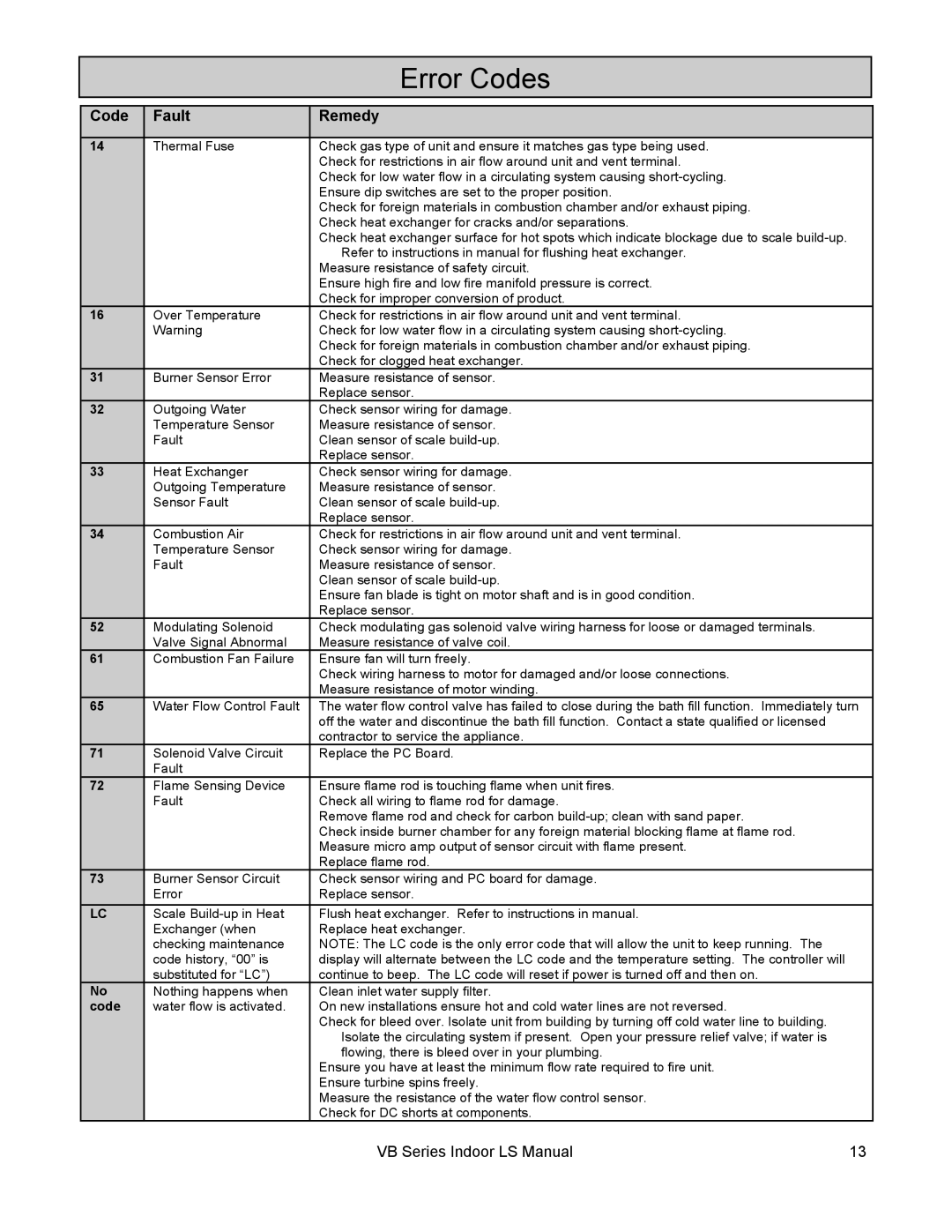
| Error Codes |
|
|
|
|
|
Code | Fault | Remedy |
|
|
|
|
|
14 | Thermal Fuse | Check gas type of unit and ensure it matches gas type being used. |
|
|
| Check for restrictions in air flow around unit and vent terminal. |
|
|
| Check for low water flow in a circulating system causing |
|
|
| Ensure dip switches are set to the proper position. |
|
|
| Check for foreign materials in combustion chamber and/or exhaust piping. |
|
|
| Check heat exchanger for cracks and/or separations. |
|
|
| Check heat exchanger surface for hot spots which indicate blockage due to scale |
|
|
| Refer to instructions in manual for flushing heat exchanger. |
|
|
| Measure resistance of safety circuit. |
|
|
| Ensure high fire and low fire manifold pressure is correct. |
|
|
| Check for improper conversion of product. |
|
16 | Over Temperature | Check for restrictions in air flow around unit and vent terminal. |
|
| Warning | Check for low water flow in a circulating system causing |
|
|
| Check for foreign materials in combustion chamber and/or exhaust piping. |
|
|
| Check for clogged heat exchanger. |
|
31 | Burner Sensor Error | Measure resistance of sensor. |
|
|
| Replace sensor. |
|
32 | Outgoing Water | Check sensor wiring for damage. |
|
| Temperature Sensor | Measure resistance of sensor. |
|
| Fault | Clean sensor of scale |
|
|
| Replace sensor. |
|
33 | Heat Exchanger | Check sensor wiring for damage. |
|
| Outgoing Temperature | Measure resistance of sensor. |
|
| Sensor Fault | Clean sensor of scale |
|
|
| Replace sensor. |
|
34 | Combustion Air | Check for restrictions in air flow around unit and vent terminal. |
|
| Temperature Sensor | Check sensor wiring for damage. |
|
| Fault | Measure resistance of sensor. |
|
|
| Clean sensor of scale |
|
|
| Ensure fan blade is tight on motor shaft and is in good condition. |
|
|
| Replace sensor. |
|
52 | Modulating Solenoid | Check modulating gas solenoid valve wiring harness for loose or damaged terminals. |
|
| Valve Signal Abnormal | Measure resistance of valve coil. |
|
61 | Combustion Fan Failure | Ensure fan will turn freely. |
|
|
| Check wiring harness to motor for damaged and/or loose connections. |
|
|
| Measure resistance of motor winding. |
|
65 | Water Flow Control Fault | The water flow control valve has failed to close during the bath fill function. Immediately turn | |
|
| off the water and discontinue the bath fill function. Contact a state qualified or licensed |
|
|
| contractor to service the appliance. |
|
71 | Solenoid Valve Circuit | Replace the PC Board. |
|
| Fault |
|
|
72 | Flame Sensing Device | Ensure flame rod is touching flame when unit fires. |
|
| Fault | Check all wiring to flame rod for damage. |
|
|
| Remove flame rod and check for carbon |
|
|
| Check inside burner chamber for any foreign material blocking flame at flame rod. |
|
|
| Measure micro amp output of sensor circuit with flame present. |
|
|
| Replace flame rod. |
|
73 | Burner Sensor Circuit | Check sensor wiring and PC board for damage. |
|
| Error | Replace sensor. |
|
LC | Scale | Flush heat exchanger. Refer to instructions in manual. |
|
| Exchanger (when | Replace heat exchanger. |
|
| checking maintenance | NOTE: The LC code is the only error code that will allow the unit to keep running. The |
|
| code history, “00” is | display will alternate between the LC code and the temperature setting. The controller will |
|
| substituted for “LC”) | continue to beep. The LC code will reset if power is turned off and then on. |
|
No | Nothing happens when | Clean inlet water supply filter. |
|
code | water flow is activated. | On new installations ensure hot and cold water lines are not reversed. |
|
|
| Check for bleed over. Isolate unit from building by turning off cold water line to building. |
|
|
| Isolate the circulating system if present. Open your pressure relief valve; if water is |
|
|
| flowing, there is bleed over in your plumbing. |
|
|
| Ensure you have at least the minimum flow rate required to fire unit. |
|
|
| Ensure turbine spins freely. |
|
|
| Measure the resistance of the water flow control sensor. |
|
|
| Check for DC shorts at components. |
|
|
| VB Series Indoor LS Manual | 13 |