REU-VB2528FFUD-US
Table of Contents
RL75i RL94i R98LSi
Specifications
Description of Operation
Consumer Safety Information
Safety Definitions
Safety Behaviors and Practices Safety Features
MC-91-1US & MCC-91-1US
Temperature Controller
MC-91 MCC-91 MC-100 BC-100 MC-502 Description
Features Available on Temperature Controllers
Features
Operating Instructions
Model Temperature Settings Available ºF
How to Set the Temperature
Temperature Controller Settings
MCC-91 Temperature Controller
Temperature Options Without a Temperature Controller
Setting the Sound Volume Voice Prompt
Re-setting the Maximum Temperature RL75 and RL94 only
Overview
Using the Water Smart / Bath Fill Function
Setting the Water Volume
Models MC-91 and MCC-91
Setting Controller to Mute
Setting the Clock
Filling the Tub
Maintenance
Code Fault Remedy
Error Codes
Code
Water Quality
Trouble Shooting for Common Issues
Accessing Operating Information
Circulating Pump
Flushing the Heat Exchanger Error Code LC or
General Instructions
Installation Instructions
Attachment of the Water Heater
Clearances from Appliance
General Instructions
Electrical Connection
Gas Piping
Pipe Sizing Procedure Example
Water Piping
Isolation Valves Installation Instructions
Pressure Relief Valve Installation Instructions
Pressure Relief Valve Maintenance
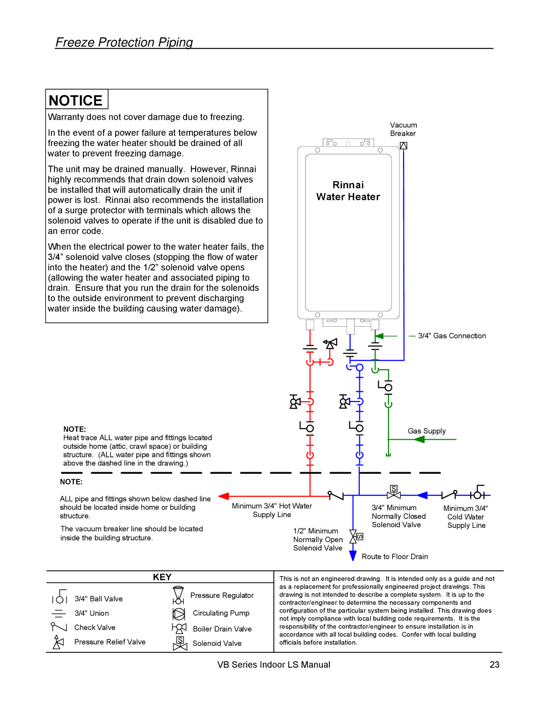
Freeze Protection
Piping Requirements
Pressure Relief Valve Requirements
Manual draining of the water heater
When the water heater or external piping has frozen
Freeze Protection
KEY
Freeze Protection Piping
Rinnai Water Heater
Recommended Piping for Basic Installation
For this application
Recommended Piping for Circulation Systems
Condensate
Venting Instructions
Intake / Exhaust Guidelines
Maximum Vent Length
Manufacturer Product Parts
Vent Products
Flue Terminal Clearances ANS Z21.10.3, CSA
Description Canadian Installations US Installations
Inside Corner
Additional Clearances Vent Terminal
Flue Installation Concentric Venting RL75i, RL94i
Venting Clearances to Combustibles
Flue Installation R98LSi, R98LSi-ASME
Air Intake Assembly
Exhaust Pipe Assembly
Vertical Terminations
Horizontal with Concentric Termination
Guidelines
Connecting Multiple Water Heaters
High Altitude Installations
Number Connected Accessories Necessary Water Heaters
Canada only
Cable Lengths and Size
Temperature Controller Installation
Configurations
Location
Outline of Remote
Mounting the Controller
Operating Instructions
For Your Safety Read Before Operating
Outlet Flow Data
Technical Data
Pressure Drop Curve
Pumps
Temperature Setting
Replacement
Space Heating
RL75i, RL94i R98LSi, R98LSi-ASME
Dimensions
Ladder Diagram for RL75i and RL94i
HOT
Ladder Diagram for R98LSi and R98LSi-ASME
Consumer Support
Warranty Information
Limited Warranty
What will Rinnai do?
Important In the State of Massachusetts 248 CMR 4.00
State Regulations
Instructions dutilisation
Instructions d’installation
Temp. d’eau
Instructions dutilisation
Model Plages de température disponible ºF
Plages de température avec un contrôleur de température
Options de température sans contrôleur à distance
Nettoyage
Entretien
Instructions générales
Fixation du chauffe-eau
Écartements par rapport à lappareil
Instructions générales
Installation à altitude élevée
Tuyauterie de gaz
Valve à Bille / Valve de dégagement de pression RL75i, RL94i
Tuyauterie deau
Soupape de sûreté
Qualité de leau
Légende
Tuyauterie recommandée pour installation de base
Condensat
Instructions de ventilation
Consignes pour aspiration/évacuation
12.5 m 10.7 m
Longueur maximum de ventilation
Horizontale
Produits de ventilation
Constructeur Produit Pièces
Nest PAS Permise
Espacements pour terminaison de cheminée ANS Z21.10.3, CSA
Installation de conduit de cheminée RL75i, RL94i
Terminaisons horizontales
Installation de conduit de cheminée R98LSi, R98LSi-ASME
Ensemble de prise dair
Montage du tuyau dévacuation
Terminaisons verticales
Terminaison horizontale concentrique
VanneMa ualmanuelleValve
Instructions dutilisation
Phase
Diagramme en escalier RL75i, RL94i
Phase TRE NEU RAL
Diagramme en escalier R98LSi, R98LSiASME
Combien de temps dure la couverture ?
Support à la clientèle
Informations sur la garantie
Quest-ce qui est couvert ?
Que fait Rinnai pour exercer la garantie ?
VB Series Indoor LS Manual
VB Series Indoor LS Manual
VB Series Indoor LS Manual
VB2528FFU VB2735FFU VA3237FFU