SECTION 4: SPECIFICATIONS

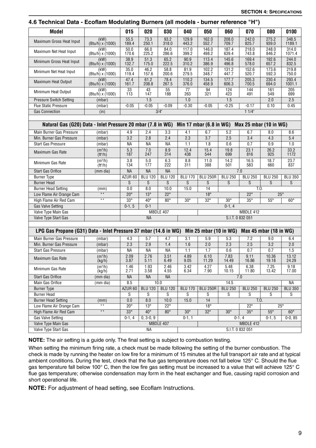
4.6 Technical Data - Ecoflam Modulating Burners (all models - burner reference "H")

Model


015

020


030

040

050

060

070

080

0100


Maximum Gross Heat Input

(kW)

55.5

73.3


93.2

129.9

162.0

208.0

242.0

275.2

348.5

(Btu/h) x (1000)

189.4

250.1


318.0

443.2

552.7

709.7

825.7

939.0

1189.1


Maximum Net Heat Input

(kW)

50.0

66.0


84.0

117.0

146.0

187.4

218.0

248.0

314.0

(Btu/h) x (1000)

170.6

225.2


286.6

399.2

498.2

639.4

743.8

846.2

1071.4


Minimum Gross Heat Input

(kW)

38.9

51.3


65.2

90.9

113.4

145.6

169.4

192.6

244.0

(Btu/h) x (1000)

132.7

175.0


222.5

310.2

386.9

496.8

578.0

657.2

832.5


Minimum Net Heat Input

(kW)

35.0

46.2


58.8

81.9

102.2

131.2

152.6

173.6

219.8

(Btu/h) x (1000)

119.4

157.6


200.6

279.5

348.7

447.7

520.7

592.3

750.0


Maximum Heat Output

(kW)

47.4

61.2


78.4

110.2

134.5

177.7

205.3

230.4

293.4

(Btu/h) x (1000)

161.7

208.8


267.5

376.0

458.9

606.3

700.5

694.0

1001.1


Minimum Heat Output

(kW)

33

43


55

77

94

124

144

161

205

(Btu/h) x (1000)

113

147


188

263

321

423

491

549

699


Pressure Switch Setting

(mbar)


1.5


1.0


1.5


2.0

2.5

Flue Static Pressure

(mbar)

-0.05

-0.05


-0.09

-0.30

-0.05

-0.25

-0.17

0.10

0.45

Gas Connection

(in)


3/4"


1 1/4"


Natural Gas (G20) Data - Inlet Pressure 20 mbar (7.8 in WG)

Min 17 mbar (6.8 in WG) Max 25 mbar (10 in WG)

Main Burner Gas Pressure

(mbar)

4.9

2.4

3.3

4.1

6.7

5.2


6.7


8.0


8.6

Min. Burner Gas Pressure

(mbar)

3.2

2.8

2.4

2.3

3.7

2.5


3.4


4.3


5.4

Start Gas Pressure

(mbar)

NA

NA

NA

1.1

1.8

0.6


0.7


0.9


1.0

Maximum Gas Rate

(m3/h)

5.3

7.0

8.9

12.4

15.4

19.8


23.1


26.2


33.2

(ft3/h)

187

247

314

438

544

699


816


925


1172

Minimum Gas Rate

(m3/h)

3.8

5.0

6.3

8.8

11.0

14.2


16.5


18.7


23.7

(ft3/h)

134

177

222

311

388

501


583


660


837


Start Gas Orifice

(mm dia)

NA

NA

NA


7.0


Burner Type


AZUR 60

BLU 120

BLU 120

BLU 170

BLU 250R

BLU 250


BLU 250


BLU 250


BLU 350

Burner Head


S

S

S

S

S

S


S


S


S

Burner Head Setting

(mm)

0.0

8.0

10.0

15.0

14


T.O.


Low Flame Air Orange Cam

**

20°

13°

22°


18°


22°


25°


High Flame Air Red Cam

**

33°

40°

80°

30°

32°

30°


35°


55°


60°

Gas Valve Setting


0-1, 5

0-1


0-1, 4


Valve Type Main Gas


MBDLE 407


MBDLE 412


Valve Type Start Gas


NA


S.I.T. 0 832 051


LPG Gas Propane (G31) Data - Inlet Pressure 37 mbar (14.6 in WG) Min 25 mbar (10 in WG)

Max 45 mbar (18 in WG)

Main Burner Gas Pressure

(mbar)

4.3

5.7

4.7

3.1

5.9

5.3

7.2


9.0


6.4

Min. Burner Gas Pressure

(mbar)

2.3

2.9

1.4

1.6

2.0

2.3

2.5


3.2


2.0

Start Gas Pressure

(mbar)

NA

NA

NA

1.1

1.7

0.6

0.7


0.7


1.5

Maximum Gas Rate

(m3/h)

2.09

2.76

3.51

4.89

6.10

7.83

9.11


10.36


13.12

(kg/h)

3.87

5.11

6.49

9.05

11.29

14.49

16.86


19.18


24.29


Minimum Gas Rate

(m3/h)

1.46

1.93

2.46

3.42

4.27

5.48

6.38


7.25


9.18

(kg/h)

2.71

3.58

4.55

6.34

7.90

10.15

11.80


13.42


17.00


Start Gas Orifice

(mm dia)

NA

NA

NA


7.0


Main Gas Orifice

(mm dia)

8.5

10.0


14.5


NA

Burner Type


AZUR 60

BLU 120

BLU 120

BLU 170

BLU 250R

BLU 250

BLU 250


BLU 250


BLU 350

Burner Head


S

S

S

S

S

S

S


S


S

Burner Head Setting

(mm)

0.0

8.0

10.0

15.0

14


T.O.


Low Flame Air Orange Cam

**

20°

13°

22°


18°


22°


25°


High Flame Air Red Cam

**

33°

40°

80°

30°

32°

30°

35°


55°


60°

Gas Valve Setting


0-1, 4

0, 3-0, 9


0-1, 1


0-1, 4


0-1, 5


0-0, 85

Valve Type Main Gas


MBDLE 407


MBDLE 412


Valve Type Start Gas


NA


S.I.T. 0 832 051


NOTE: The air setting is a guide only. The final setting is subject to combustion testing.

When setting the minimum firing rate, a check must be made following the setting of the burner combustion. The check is made by running the heater on low fire for a minimum of 15 minutes at the full transport air rate and at typical ambient conditions. During the test, check that the flue gas temperature does not fall below 125° C. Should the flue gas temperature fall below 100° C, then the low fire gas setting must be increased to a value that will achieve 125° C flue gas temperature; otherwise condensation may form in the heat exchanger and flue, causing rapid corrosion and short operational life.

NOTE: For adjustment of head setting, see Ecoflam Instructions.

9

Page 15
Image 15
Roberts Gorden POP-ECA/PGP-ECA 015 to 0100 Min 17 mbar 6.8 in WG Max 25 mbar 10 in WG, Maximum Gross Heat Input

POP-ECA/PGP-ECA 015 to 0100 specifications

The Roberts Gordon POP-ECA/PGP-ECA 015 to 0100 series represents a significant advancement in the realm of heating technologies, particularly in industrial and commercial applications. These innovative units are designed to provide efficient, reliable heating solutions tailored to meet the diverse needs of various environments.

Main features of the POP-ECA/PGP-ECA series include their high-performance heating capabilities, which allow for rapid temperature rise and consistent heating throughout a space. This efficiency is critical for industries that require precise temperature control for their processes. The units are engineered to emit heat evenly, reducing hot spots and ensuring that the entire area is warmed effectively.

One of the standout technologies incorporated into these heaters is their advanced combustion system. This system optimizes fuel usage, enhancing energy efficiency while minimizing emissions. This aspect is particularly vital in today’s environmentally conscious world, where businesses seek to reduce their carbon footprint. The designs are compliant with current environmental regulations, making them suitable for use in various operational settings.

The POP-ECA/PGP-ECA series also boasts a variety of innovative features aimed at user convenience. Integrated control systems allow for easy adjustments and monitoring, enabling operators to maintain ideal temperature settings with minimal effort. Additionally, many units in the series offer flexible mounting options, allowing for vertical or horizontal installation to suit different space constraints and layout requirements.

Characteristics of the POP-ECA/PGP-ECA series also include robust construction, ensuring durability and longevity even in the most demanding environments. The materials used are resistant to corrosion and wear, providing a reliable heating solution that requires minimal maintenance over time. Moreover, the compact design of the units means that they can be installed in tight spaces without sacrificing performance.

Overall, the Roberts Gordon POP-ECA/PGP-ECA 015 to 0100 series stands as a testament to cutting-edge engineering in heating technology. With their combination of efficiency, environmentally conscious design, and user-friendly features, these units are an excellent choice for a wide range of industrial and commercial heating applications. They exemplify the future of heating solutions, prioritizing performance while remaining mindful of energy consumption and environmental impact.