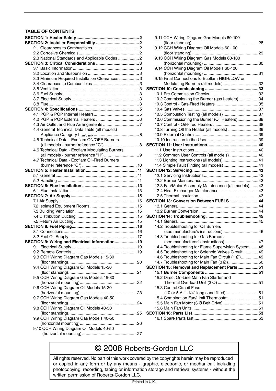
POP-ECA/PGP-ECA 015 to 0100 specifications
The Roberts Gordon POP-ECA/PGP-ECA 015 to 0100 series represents a significant advancement in the realm of heating technologies, particularly in industrial and commercial applications. These innovative units are designed to provide efficient, reliable heating solutions tailored to meet the diverse needs of various environments.Main features of the POP-ECA/PGP-ECA series include their high-performance heating capabilities, which allow for rapid temperature rise and consistent heating throughout a space. This efficiency is critical for industries that require precise temperature control for their processes. The units are engineered to emit heat evenly, reducing hot spots and ensuring that the entire area is warmed effectively.
One of the standout technologies incorporated into these heaters is their advanced combustion system. This system optimizes fuel usage, enhancing energy efficiency while minimizing emissions. This aspect is particularly vital in today’s environmentally conscious world, where businesses seek to reduce their carbon footprint. The designs are compliant with current environmental regulations, making them suitable for use in various operational settings.
The POP-ECA/PGP-ECA series also boasts a variety of innovative features aimed at user convenience. Integrated control systems allow for easy adjustments and monitoring, enabling operators to maintain ideal temperature settings with minimal effort. Additionally, many units in the series offer flexible mounting options, allowing for vertical or horizontal installation to suit different space constraints and layout requirements.
Characteristics of the POP-ECA/PGP-ECA series also include robust construction, ensuring durability and longevity even in the most demanding environments. The materials used are resistant to corrosion and wear, providing a reliable heating solution that requires minimal maintenance over time. Moreover, the compact design of the units means that they can be installed in tight spaces without sacrificing performance.
Overall, the Roberts Gordon POP-ECA/PGP-ECA 015 to 0100 series stands as a testament to cutting-edge engineering in heating technology. With their combination of efficiency, environmentally conscious design, and user-friendly features, these units are an excellent choice for a wide range of industrial and commercial heating applications. They exemplify the future of heating solutions, prioritizing performance while remaining mindful of energy consumption and environmental impact.

