Controls and Functions
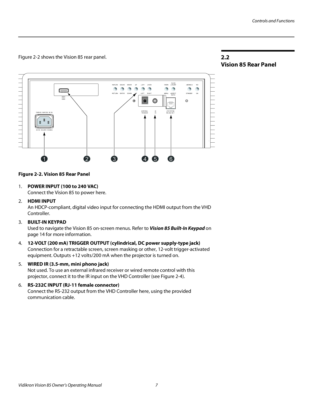
Figure 2-2 shows the Vision 85 rear panel.
RETURN | ENTER | DOWN | UP | LEFT | RIGHT |
| MENU | RATIO | STANDBY | ON |
| ASPECT | |||||||||
RETURN | ENTER | DOWN | UP | LEFT | RIGHT |
| MENU | ASPECT | STANDBY | ON |
|
|
|
|
|
|
|
| RATIO |
|
|
HDMI |
|
|
|
|
|
|
|
|
|
|
HDMI |
|
|
|
|
|
|
|
|
|
|
|
|
| TRIGGER | IR | OUT |
|
| |||
|
|
| TRIGGER | IR |
|
| ||||
|
|
|
|
|
| |||||
AC IN
1 | 2 | 3 | 4 | 5 | 6 |
Figure 2-2. Vision 85 Rear Panel
1.POWER INPUT (100 to 240 VAC) Connect the Vision 85 to power here.
2.HDMI INPUT
An
3.BUILT-IN KEYPAD
Used to navigate the Vision 85
4.
5.WIRED IR (3.5-mm, mini phono jack)
Not used. To use an external infrared receiver or wired remote control with this projector, connect it to the IR input on the VHD Controller (see Figure
6.RS-232C INPUT (RJ-11 female connector)
Connect the
2.2
Vision 85 Rear Panel
Vidikron Vision 85 Owner’s Operating Manual | 7 |